Quick install guide 5, Install cam (optional), Place the switch in its operating location – Allied Telesis AT-9800 SERIES User Manual
Page 5: Apply ac power to the switch (for ac models), Ac power at-rps8000 rps connector compact flash, At-9816gf
Quick Install Guide
5
C613-04038-01 REV D
5.
Install CAM (Optional)
If you purchased a Content Addressable Memory (CAM) module, install it
now by following the instructions in the CAM Quick Install Guide.
The CAM Quick Install Guide can be found on the AT-9800 Series
Documentation and Tools CD-ROM, or can be downloaded from
www.alliedtelesyn.co.nz/support/at9800/.
6.
Place the switch in its operating location
If installing the switch in a rack:
•
Remove the rubber feet
•
Attach the rack-mounting brackets
•
Mount the switch in the rack
7.
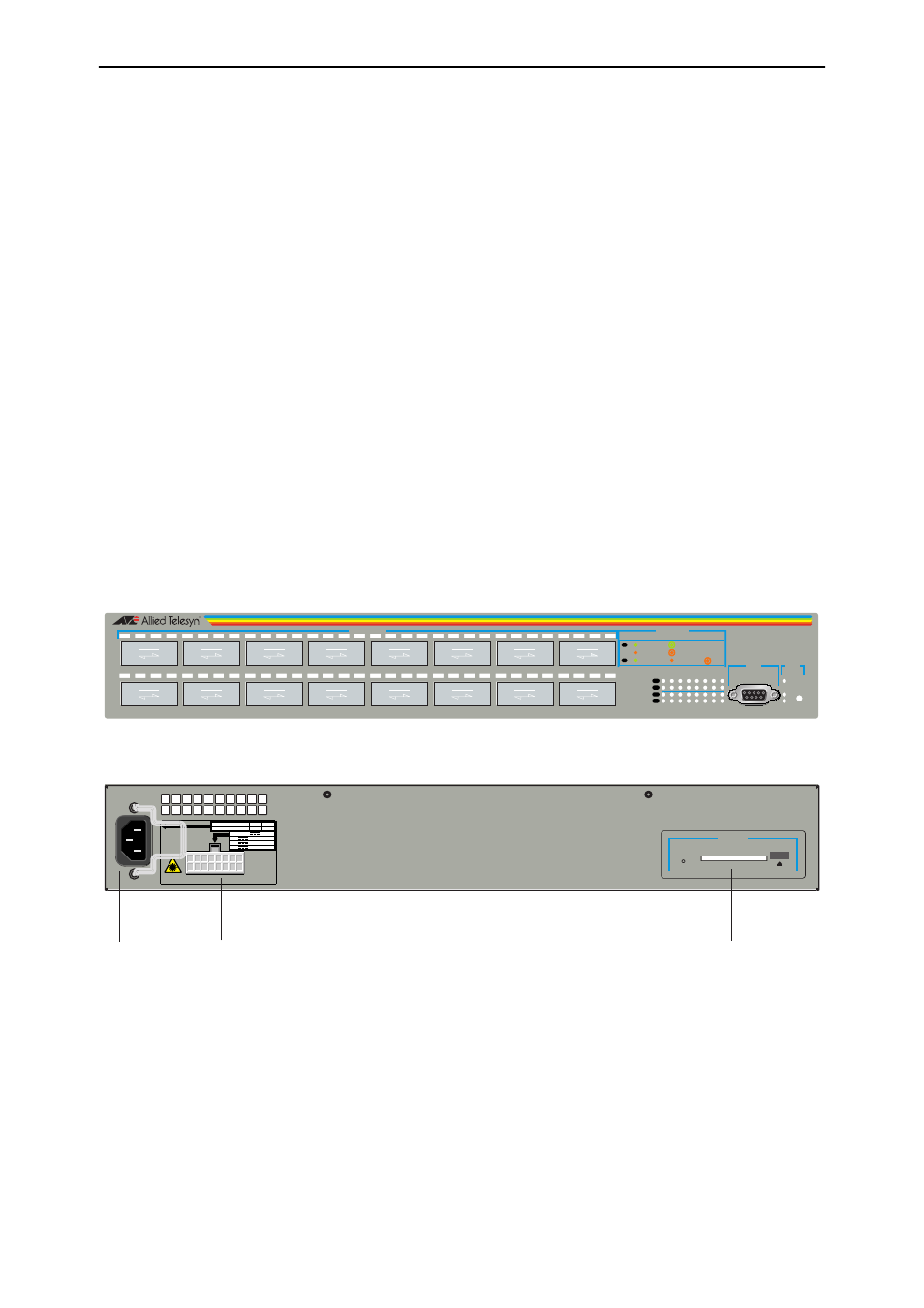
Apply AC power to the switch (for AC models)
Plug the power cord into the AC power connector on the switch’s rear
panel. The Fault LED should flash for approximately 10 seconds as the
switch runs internal tests.
If the LED continues to flash or remains lit, refer to the AT-9800 Series
Hardware Reference for troubleshooting information.
Figure 1: AT-9816GF front panel and rear panel with AC power inlet.
8.
Apply DC power to the switch (for DC models)
Read the Safety and Statutory Information booklet before connecting a DC
power supply. A copy of this booklet is included with each switch. It is also
included on the Documentation and Tools CD-ROM, or can be
downloaded from www.alliedtelesyn.co.nz/support/at9800/.
CLASS 1
LASER
R.P.S.
INPUT
AC SUPPLY DATA
100-120/200-240
~
HZ
50/60
AMPS
4/2
Input Vdc
+3.3
+5
+12
A Max
13
8
1
COMPACT FLASH
ACTIVITY
AC Power
AT-RPS8000 RPS Connector
Compact FLASH
STATUS
RESET
FAULT
PWR
RPS
1
9
2
10
3
11
4
12
5
13
6
14
7
15
8
16
1
2
3
4
5
6
7
8
9
10
11
12
13
14
15
16
RS-232
TERMINAL PORT
L /A
GBIC
L /A
GBIC
ASYN0
1000BASE-X GBIC
AT-9816GF
Multi-Layer Gigabit Switch
PORT ACTIVITY
L /A
LINK / FULL DUP
ACTIVITY
LINK / HALF DUP
ACTIVITY
L /A
L /A
ENABLED
DISABLED
FAULT
GBIC
L /A
L /A
GBIC