Front and back panel components, Status leds, Front and back panel components status leds – Allied Telesis AT-MCF12VF, SM User Manual
Page 11: At-mcf6xx and at-mcf12xx installation guide 3
AT-MCF6xx and AT-MCF12xx Installation Guide
3
Front and Back Panel Components
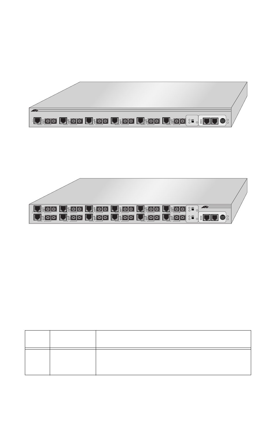
This section describes the features and components of the AT-MCF6xx and
AT-MCF12xx Series Multichannel Media Converters. Figure 1 illustrates the
front panel of an AT-MCF6xx system.
Figure 1 Front Panel of the AT-MC6xx Multichannel Media Converter
(Model AT-MCF6SC)
Figure 2 illustrates the front panel of an AT-MCF12xx Series system.
Figure 2 Front Panel of the AT-MCF12xx Series Multichannel Media Converter
(Model AT-MCF12SC)
Status LEDs
The media converter does not require any software configuration or software
management. The status of the unit can be determined by viewing the LEDs
on the front of the unit. Table 2 lists the functions of the power supply and
Link Test switch LEDs.
Table 2 Power Supply and Link Test Switch LEDs
LED
Color
Indicates
MAIN
Green
Flashing Green
The main power supply is functioning normally.
The main power supply is failing or has failed.
RESET
LINK TEST
NORM
TEST
Tx
Rx
Tx
Rx
Tx
Rx
Tx
Rx
Tx
Rx
Tx
Rx
T-LNK
F-LNK
Active
MCF6SC
10Base-TX/FX Media Converter
MANAGEMENT
LNK
REC
STATION
HUB
OR
10Base-T
RS232
P O W E R
BCKP
MAIN
Ready
1
2
3
4
5
6
RESET
7-12 LINK TEST
NORM
TEST
MCF12SC
10Base-TX/FX Media Converter
MANAGEMENT
LNK
REC
STATION
HUB
OR
10Base-T
RS232
P O W E R
BCKP
MAIN
Ready
Tx
Rx
Tx
Rx
Tx
Rx
Tx
Rx
Tx
Rx
Tx
Rx
7
8
9
10
11
12
Tx
Rx
Tx
Rx
Tx
Rx
Tx
Rx
Tx
Rx
Tx
Rx
T-LNK
F-LNK
Active
1
2
3
4
5
6
RESET
1-6 LINK TEST
NORM
TEST