Installing the switch on a desktop, Figure 6. attaching the rubber feet – Allied Telesis AT-FS750/24 User Manual
Page 31
AT-FS750/16 and AT-FS750/24 Fast Ethernet Smart Switches Installation Guide
31
Installing the Switch on a Desktop
You can install the AT-FS750/16 and AT-FS750/24 Fast Ethernet Smart
Switches on a desktop or in a standard 19-inch equipment rack. To install
the switch in a rack, refer to “Installing the Switch in an Equipment Rack”
on page 32.
To place the switch on a desktop, perform the following procedure:
1. Remove all equipment from the package and store the packaging
material in a safe place.
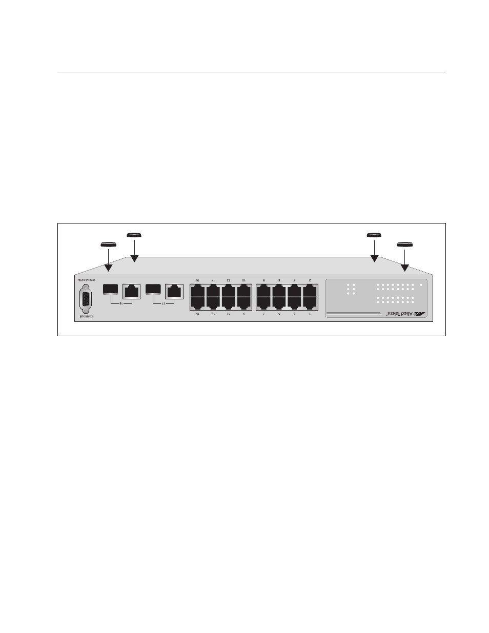
2. Turn the switch over and attach the four rubber feet to the bottom of
the switch as shown in Figure 6.
Figure 6. Attaching the Rubber Feet
3. Turn the switch over again and place it on a flat, secure surface (such
as a desk or table) leaving ample space around the unit for ventilation.
1292
LINK/AC
T
SPEED
LINK/AC
T
SPEED
POWER
17
18
LINK/AC
T
1
3
5
7
9
11
13
15
2
4
6
8
10
12
14
16
1000M
100M
AT-FS750/16
16-Por
t 10/100Mbps + 2 SFP/1000T Combo We
bSmart Switch