Front and back panels – Allied Telesis AT-FS750/24 User Manual
Page 17
AT-FS750/16 and AT-FS750/24 Fast Ethernet Smart Switches Installation Guide
17
Front and Back Panels
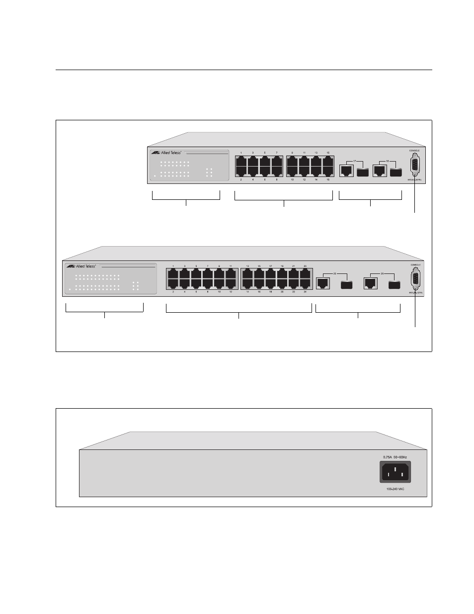
Figure 1 illustrates the front panels of the AT-FS750/16 and AT-FS750/24
Fast Ethernet Smart Switches.
Figure 1. AT-FS750/16 and AT-FS750/24 Front Panels
Figure 2 illustrates the back panel of the AT-FS750/16 and AT-FS750/24
Fast Ethernet Smart Switches.
Figure 2. AT-FS750/16 and AT-FS750/24 Back Panels
10/100Base Twisted Pair
AT-FS750/16
1288
LINK/ACT
SPEED
LINK/ACT
SPEED
POWER
17
18
LINK/ACT
1
3
5
7
9
11
13
15
2
4
6
8
10
12
14
16
1000M
100M
AT-FS750/16
16-Port 10/100Mbps + 2 SFP/1000T Combo WebSmart Switch
Port and System LEDs
Console Port
Uplink Combo Ports
Ports
10/100Base Twisted Pair Ports
Port and System LEDs
AT-FS750/24
SFP Ports
1290
1
3
5
7
9
11
13
15
17
19
21
23
POWER
2
4
6
8
10
12
14
16
18
20
22
24
25
26
LINK/ACT
LINK/ACT
SPEED
LINK/ACT
SPEED
AT-FS750/24
24-Port 10/100Mbps + 2 SFP/1000T Combo WebSmart Switch
1000M
100M
Console Port
Uplink Combo Ports
AT-FS750/16 and AT-FS750/24
807