At-8000s/48 front panel, At-8000s/48 back panel, At-8000s/48 front panel at-8000s/48 back panel – Allied Telesis AT-8000S User Manual
Page 13
Product Description
Page 13
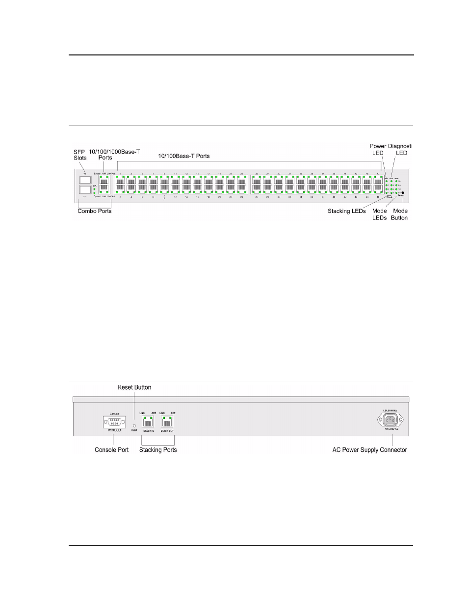
AT-8000S/48 Front Panel
The following figure illustrates the AT-8000S/48 front panel.
Figure 7:
AT-8000S/48 Front Panel
The AT-8000S/48 device front panel is configured as follows:
•
48 10/100Mbps Ports — RJ-45 ports designated as 10/100Base-T. The RJ-45 ports are designated as ports
Ports 1 - 48.
•
2 10/100/1000Base-T Copper Ports — There are two copper 10/100/100Base-T ports designated on the
switch as ports 49R and 50R. These ports are paired with the two SFP slots designated on the switch as
ports 49 and 50. Together these four ports form the Combo ports shown in
..
•
2 SFP Ports — There are two SFP slots which support either a 100Base-FX or a 1000Base-X (fiber)
connection and are designated on the switch as ports 49 and 50. This SFP slot is paired with the two 10/100/
1000Base-T copper ports which is designated on the switch as port 49R and 50R. Together these four ports
form the Combo ports shown in
.
•
Mode Button — Selects the port LED indications.
AT-8000S/48 Back Panel
The following figure illustrates the AT-8000S/48 back panel.
Figure 8:
AT-8000S/48 Back Panel
The AT-8000S/48 back panel is configured as follows:
Power Connector — AC power supply interface.
•
2 Stacking Ports — Two RJ-45 ports device stacking.
•
Reset Button — Button to reset the device.
•
DB-9 Console port — An asynchronous serial console port supporting the RS-232 electrical specification.
The port is used to connect the device to the console managing the device.