Components, Figure 1. front panels figure 2. back panels, Chapter 1: product description 18 – Allied Telesis AT-GS900/24 User Manual
Page 18
Chapter 1: Product Description
18
Components
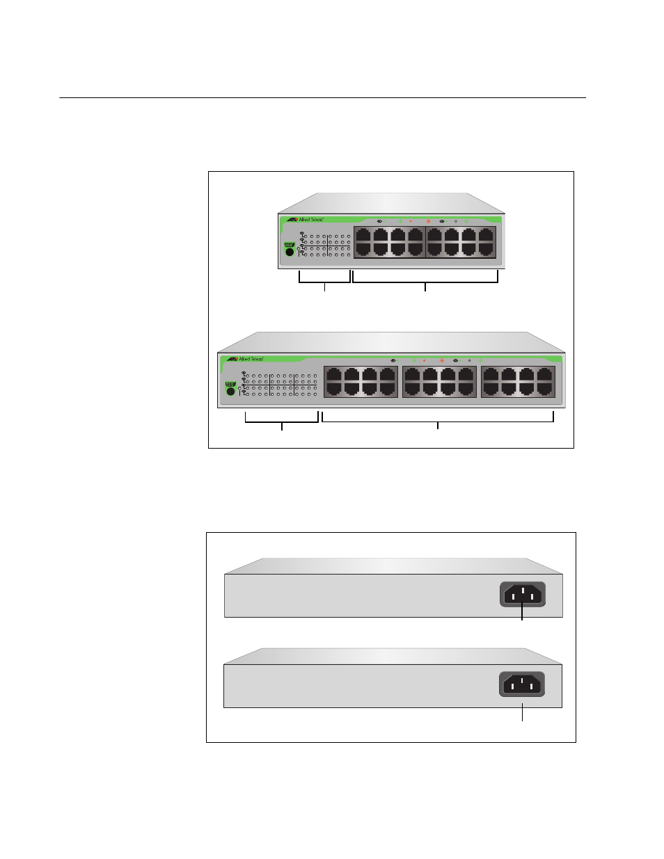
Figure 1 illustrates the front panels of the AT-GS900/16 and AT-GS900/24
switches.
Figure 1. Front Panels
Figure 2 illustrates the back panels of the AT-GS900/16 and AT-GS900/24
switches.
Figure 2. Back Panels
24 Port 10/100/1000Base-T Gigabit Ethernet Switch
1
3
5
7
9
11
13
15
17
19
21
23
2
4
6
8
10
12
14
16
18
20
22
24
18
20
22
24
10
12
14
16
2
4
6
8
9
11
13
15
1
3
5
7
17
19
21
23
POWER
10/100 LINK
ACT
1000 LINK
ACT
FDX
HDX
COL
AT-GS900/24
1897
16 - 10/100/1000Base Twisted Pair Ports
1896
AT-GS900/16
16 Port 10/100/1000Base-T Gigabit Ethernet Switch
2
4
6
8
10
12
14
16
1
3
5
7
9
11
13
15
POWER
10
12
14
16
2
4
6
8
10/100 LINK
ACT
1000 LINK
ACT
FDX
HDX
COL
9
11
13
15
1
3
5
7
System / Port LEDS
AT-GS900/16
AT-GS900/24
24 - 10/100/1000Base Twisted Pair Ports
System / Port LEDS
1899
100-240~ V A C
1899
100-240~ V A C
AC Power Connector
AT-GS900/16
AT-GS900/24
AC Power Connector