Allied Telesis x900 Series Switch and SwitchBlade x908 User Manual
Page 29
x900 Series Switch and SwitchBlade
®
x908
28
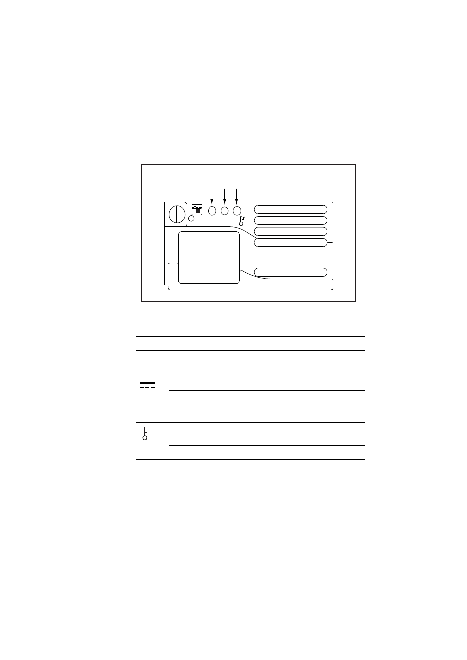
PWR05
LEDs
The following is a diagram of the LEDs in the PWR05 power supply units:
PWR05
AC
LEDs
The following table describes LEDs on the PWR05 AC power supply unit for the
SwitchBlade x908.
IN
LED
POWER
CONNECTOR
OUT
LED
FAULT
LED
LED
State
Description
~
IN
Green
AC input voltage is within 90-264 VAC, 47-63Hz.
Off
AC input voltage is outside the acceptable range.
OUT
Green
DC output voltage is within 12VDC +/- 10%.
Off
DC output voltage is outside the acceptable range, or
the Standby switch is Off. If a fault occurs then the
FAULT LED will display and the OUT LED will be Off.
FAULT
Red
A fault has occurred. There is either a fan failure, or the
temperature has exceeded its limit of 70º C (158º F).
Off
No fault conditions detected.
- AT-GS908M (54 pages)
- AT-x230-10GP (80 pages)
- AT-GS950/48PS (64 pages)
- AT-GS950/10PS (386 pages)
- AT-GS950/16PS (386 pages)
- AT-GS950/48PS (386 pages)
- AT-9000 Series (258 pages)
- AT-9000 Series (1480 pages)
- IE200 Series (70 pages)
- AT-GS950/48 (60 pages)
- AT-GS950/48 (410 pages)
- AT-GS950/8 (52 pages)
- AT-GS950/48 (378 pages)
- SwitchBlade x8106 (322 pages)
- SwitchBlade x8112 (322 pages)
- SwitchBlade x8106 (240 pages)
- SwitchBlade x8112 (240 pages)
- AT-TQ Series (172 pages)
- AlliedWare Plus Operating System Version 5.4.4C (x310-26FT,x310-26FP,x310-50FT,x310-50FP) (2220 pages)
- FS970M Series (106 pages)
- 8100L Series (116 pages)
- 8100S Series (140 pages)
- x310 Series (116 pages)
- x310 Series (120 pages)
- AT-GS950/24 (404 pages)
- AT-GS950/24 (366 pages)
- AT-GS950/16 (44 pages)
- AT-GS950/16 (404 pages)
- AT-GS950/16 (364 pages)
- AT-GS950/8 (364 pages)
- AT-GS950/8 (52 pages)
- AT-GS950/8 (404 pages)
- AT-8100 Series (330 pages)
- AT-8100 Series (1962 pages)
- AT-FS970M Series (330 pages)
- AT-FS970M Series (1938 pages)
- SwitchBlade x3112 (294 pages)
- SwitchBlade x3106 (288 pages)
- SwitchBlade x3106 (260 pages)
- SwitchBlade x3112 (222 pages)
- AT-S95 CLI (AT-8000GS Series) (397 pages)
- AT-S94 CLI (AT-8000S Series) (402 pages)
- AT-IMC1000T/SFP (23 pages)
- AT-IMC1000TP/SFP (24 pages)
- AT-SBx3106WMB (44 pages)