Allied Telesis Removable Power Supply and Fan User Manual
Page 18
Installation Guide
17
PWR05
AC
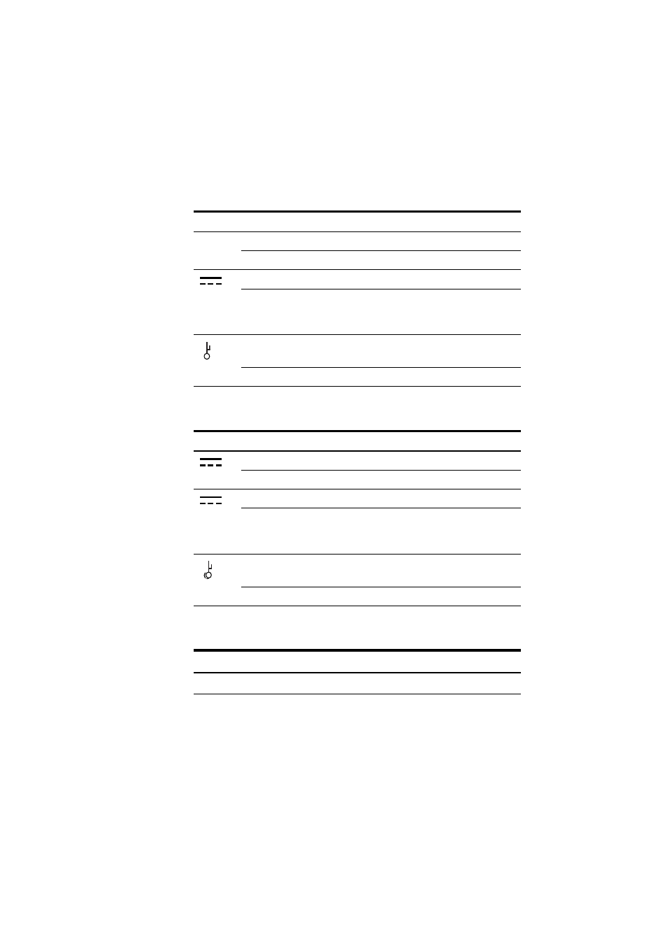
The following table describes LEDs on the PWR05 AC power supply unit.
PWR05
DC
The following table describes LEDs on the PWR05 DC power supply unit.
FAN01
The following table describes LEDs on the FAN01 fan-only module.
LED
State
Description
~
IN
Green
AC input voltage is within 90-264 VAC, 47-63Hz.
Off
AC input voltage is outside the acceptable range.
OUT
Green
DC output voltage is within 12VDC +/- 10%.
Off
DC output voltage is outside the acceptable range, or
the Standby switch is Off. If a fault occurs then the
FAULT LED will display and the OUT LED will be Off.
FAULT
Amber
A fault has occurred. There is either a fan failure, or the
temperature has exceeded its limit of 70º C (158º F).
Off
No fault conditions detected.
LED
State
Description
IN
Green
DC input voltage is within 40 VDC to 60 VDC.
Off
DC input voltage is outside the acceptable range.
OUT
Green
DC output voltage is within 12VDC +/- 10%.
Off
DC output voltage is outside the acceptable range, or
the Standby switch is Off. If a fault occurs then the
FAULT LED will display and the OUT LED will be Off.
FAULT
Amber
A fault has occurred. There is either a fan failure, or the
temperature has exceeded its limit of 70º C (158º F).
Off
No fault conditions detected.
LED
State
Description
FAULT
Red
The fan has failed.