Connecting a pwr05 dc power supply, Removable power supply and fan, Or thicker – Allied Telesis Removable Power Supply and Fan User Manual
Page 15
Removable Power Supply and Fan
14
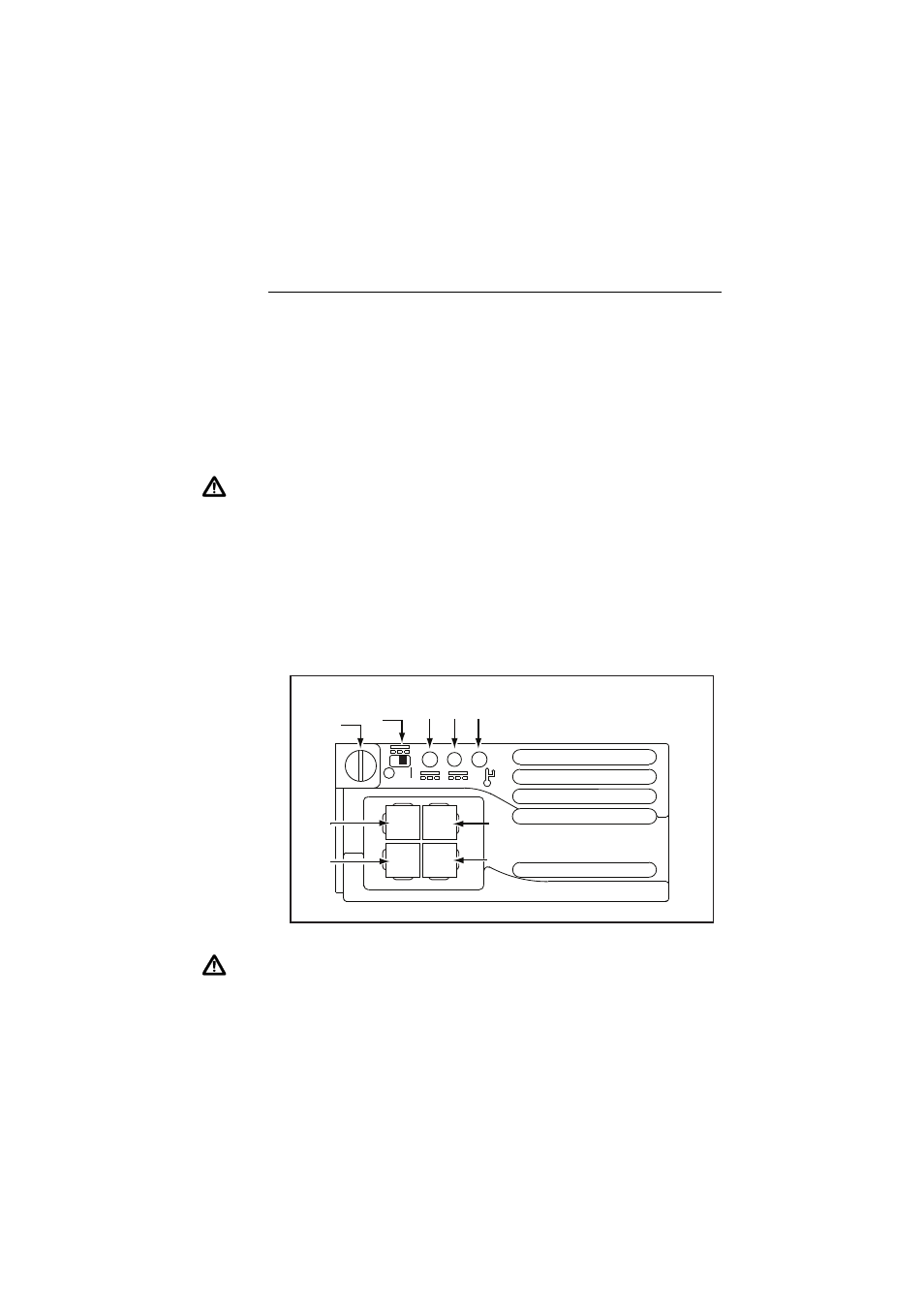
Connecting a PWR05 DC power supply
Follow these instructions to connect an AT-PWR05 DC PSU to a DC power
supply. Only trained and qualified personnel should connect a DC power supply.
You need to connect the supplied DC power cable to an appropriate DC power
source.
For centralised DC power connection, the switch should be installed in
restricted access areas only (such as dedicated equipment rooms or
equipment closets) in accordance with Articles 110-16, 110-17, and 110-18 of
the National Electrical Code, ANSI/NFPA 70.
Warning When mounting one or two AT-PWR05 DC PSUs to a grounded rack,
ensure that the ground level of the rack and the DC power connector are the
same .
Power supply specifications:
■
functional range 40 to 60 V DC, 48 V nominal
■
supports either positive grounded or negative grounded operation
■
a 30 Amp certified/listed circuit breaker is required for circuit protection
Warning When SwitchBlade x908 devices are connected with VCS stacking
cables (either HS-STK-CBL or XEM-STK-CBL), each individual stack member
chassis must be additionally grounded by using the rear grounding-terminal on
each device. In order to avoid large circulating ground currents, the wires of each
grounding cable must be 18 AWG (0.8mm
2
) or thicker.
DC
IN
LED
RUN/STANDBY
SWITCH
CAPTIVE
SCREW
DC
OUT
LED
FAULT
LED
N/C
GREEN
( GND )
RED
( + )
BLACK
( - )