Operation, Display interface, Amps – American Power Conversion AP7902 AP7911 User Manual
Page 10
6
Switched Rack PDU Installation and Quick Start
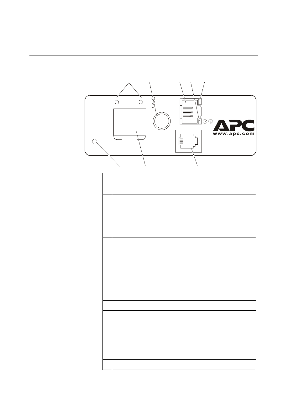
Operation
Display interface
Link - Rx/Tx
10 /100
Status
Serial Port
Reset
- Warning
- OK
- Overload
B2
B1
TOTAL
Am
ps
Amps
Amps
Switched Rack PDU
Line Indicator LED: Indicates normal (green), warning (yellow), and
alarm (red) conditions for bank 1 (B1), bank 2 (B2), or the total of the
two banks (both B1 and B2 illuminated).
Control button:
• Press and hold for five seconds to view the orientation; hold for an
additional five seconds to change the orientation.
• Press to change from B1 to B2, B2 to TOTAL, or TOTAL to B1.
Ethernet port: Connects the Rack PDU to your network, using a CAT5
network cable.
Status
LED
: Indicates the status of the Ethernet LAN connection and
the state of the
Rack PDU.
• Off–The Rack PDU has no power.
• Solid green–The Rack PDU has valid TCP/IP settings.
• Flashing green–The Rack PDU does not have valid TCP/IP
settings.
• Solid orange–A hardware failure has been detected in the Rack
PDU. Contact Customer Support at a phone number on the back
cover of this manual.
• Flashing orange–The Rack PDU is making BOOTP requests.
Link LED: Indicates whether there is activity on the network.
Serial port: Access internal menus by connecting this port (RJ-11
modular port) to a serial port on your computer, using the supplied
serial cable (940-0144).
Digital display: Displays the current used by the Rack PDU and
attached devices. Shows the aggregate current for the Rack PDU for
bank 1 (B1), bank 2 (B2), or the total current of both bank 1 and
bank 2 (TOTAL).
Reset switch: Resets the Rack PDU without affecting the outlet status.