Installation diagram – A.O. Smith ADM - 80 User Manual
Page 21
Instruction manual ADM
21
is
3.5
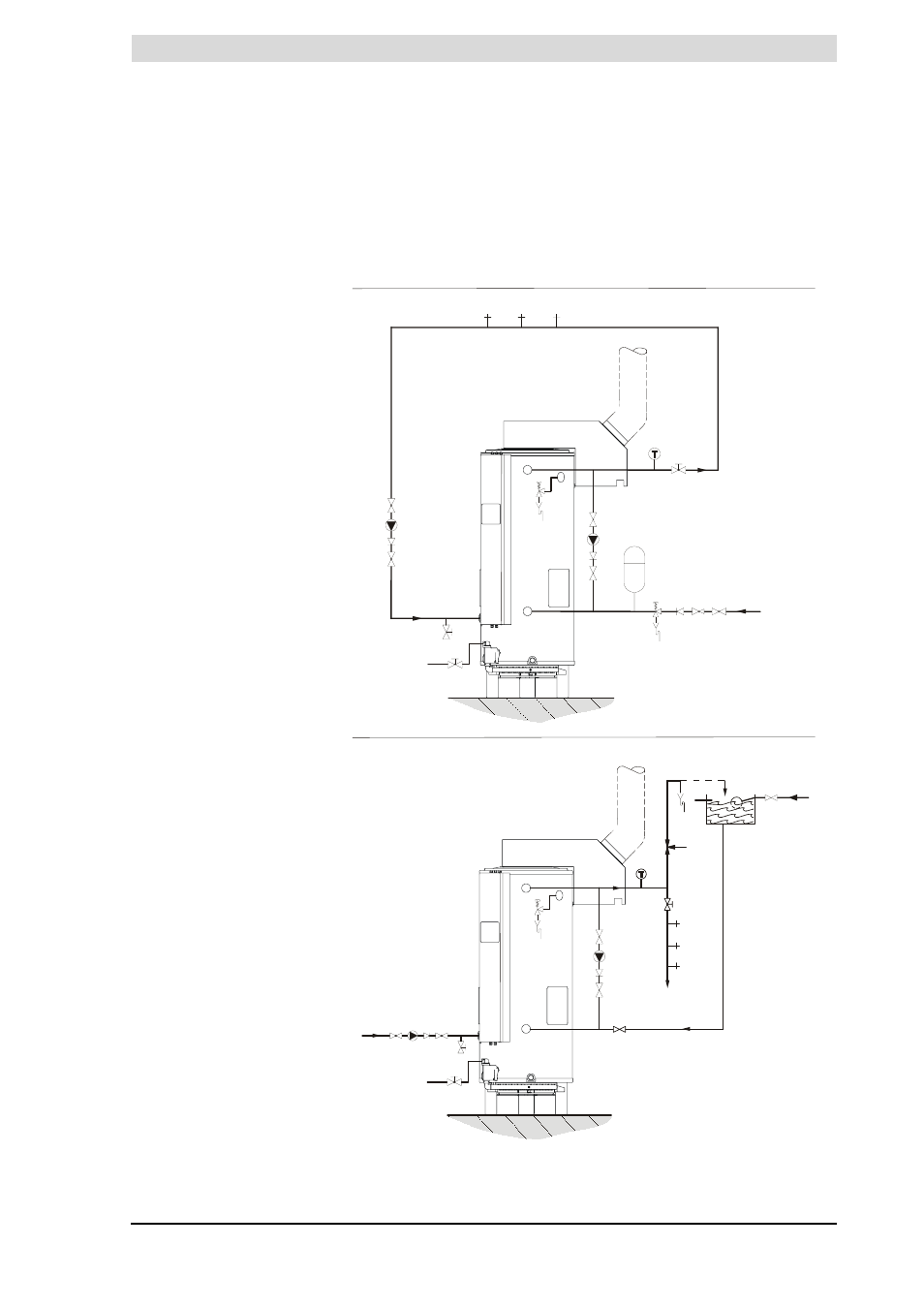
Installation diagram
3.5.1
Installation
This figure shows the installation diagram. This diagram is used in the sections
in which the actual connection process is described.
Installation diagram
Legend
Only applicable numbers are
mentioned.
1. pressure reducing valve
(mandatory)
3. T&P valve (mandatory)
4. stop valve (recommended)
5. non-return valve (mandatory)
6. circulation pump (optional)
7. top to bottom circulation pump
(optional)
9. drain valve
10. manual gas valve (mandatory)
11. service stop valve (mandatory)
12. temperature gauge
(recommended)
14. hot water draw-off points
15. expansion valve (mandatory)
16. expansion vessel (mandatory)
17. 3-way aeration valve
(recommended)
18. water tank
19. float valve
A. cold water supply
B. hot water supply
C. circulation pipe
D. gas supply
E. overflow pipe
H. overflow pipe
IMD-0466 R0
UNVENTED
VENTED
10
D
4
5
7
4
3
B
A
4
E
C
14
11
C
4
6
4
5
9
17
4
12
18
19
H
14
14
C
4
5
6
4
14
14
14
10
D
B
A
4
5 1
15
16
4
5
7
4
9
11
12
3