Asus DELUXE P4R800-V User Manual
Page 46
2-24
Chapter 2: Hardware information
7. Chassis intrusion connector (4-1 pin CHASSIS)
This lead is for a chassis designed with intrusion detection feature.
This requires an external detection mechanism such as a chassis
intrusion sensor or microswitch. When you remove any chassis
component, the sensor triggers and sends a high-level signal to this
lead to record a chassis intrusion event.
By default, the pins labeled “Chassis Signal” and “Ground” are shorted
with a jumper cap. If you wish to use the chassis intrusion detection
feature, remove the jumper cap from the pins.
P4R800-V
DELUXE
®
P4R800-V DELUXE
Chassis Alarm Lead
CHASSIS
+5VSB_MB
Chassis Signal
GND
(Default)
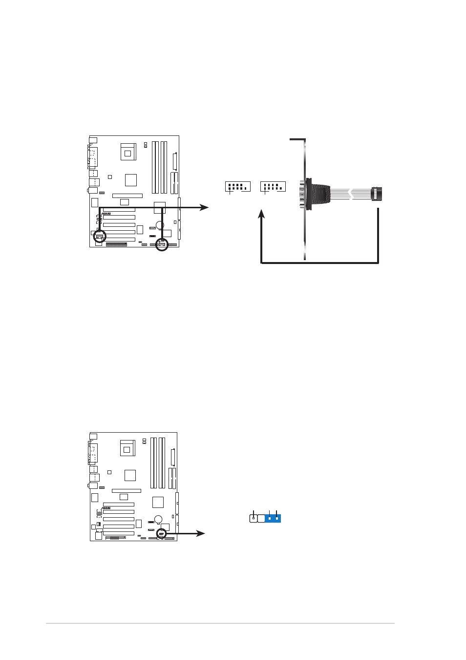
6. Serial port connectors (10-1 pin COM1, COM2)
These connectors accommodate two serial port modules. Use the
bundled 9-pin COM cable to connect the serial port module to one of
these connectors, then install the module into a slot opening at the
front or back of the system chassis.
P4R800-V
DELUXE
®
P4R800-V DELUXE
Serial COM2 Bracket
PIN 1
COM1
PIN 1
COM2