Filter shaker switch – Nilfisk-ALTO ATS 46/53 User Manual
Page 17
American-Lincoln
1-17
ATS 46/53 Battery
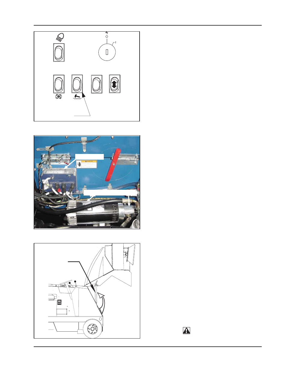
FILTER SHAKER SWITCH (See Figure 6)
The filter shaker switch is located on the instrument panel
below the ignition switch. This is a momentary switch
that will activate the filter shaker motors for 20 to 30
seconds to clear the dust control filter. The Impeller fan
will stop when the filter shaker has been activated. The
filter shaker will only operate with the hopper in the
“DOWN” position.
Use the filter shaker to clear the filter when the dust
control light comes on (warning bank) and just before
dumping the hopper.
MillipaK SEM CONTROLLER (See Figure 7)
The controller is located in the seat compartment and
includes a number of features designed to help the user
track down operational faults, wiring faults or internal
controller faults, including a flashing indicator light.
The Flash Codes are:
ON
No fault, normal condition
OFF
Internal controller fault
1 flash
Program Error
2 flashes
High Pedal Disable
3 flashes
MOSFET Short Circuit
4 flashes
Contactor fault or Motor Open Circuit
5 flashes
Not used
6 flashes
Accelerator wire off fault
7 flashes
Low or High battery voltage
8 flashes
Over temperature or timed cutback
HYDRAULIC PUMP (See Figure 7)
The pump is located in the seat compartment and is
powered by a 45 amp circuit breaker (on the power panel)
and a contact linked with the key switch. It functions at
1450 PSI and features 100 bar relief.
HOPPER SAFETY LOCK ARM (See Figure 8)
The hopper safety arm is located near the right front wheel
well. The safety arm will prevent the hopper from dropping
unexpectedly during service/maintenance.
TO ENGAGE THE SAFETY ARM:
1.
Empty hopper
2.
Set the parking brake.
3.
Raise the hopper.
4.
Lift safety arm to engage the slot on the hopper
frame.
5.
When work has been completed, return the
safey arm to the stowed position.
WARNING
When the hopper is raised the safety arm must be engaged
before ANY work is done under the hopper.
OPERATION OF CONTROLS AND GAUGES
HOPPER
SAFETY ARM
TO
ENGAGE
MODEL NO.
SERIAL NO.
C1700
C1640-2batt FIGURE 6
FIGURE 7
C1700
FIGURE 8
FILTER
SHAKER
SWITCH
CONTROLLER
PUMP MOTOR PUMP