2 controlled device connections – Campbell Scientific SDM-CD8S 8 Channel Solid State DC Control Module User Manual
Page 10
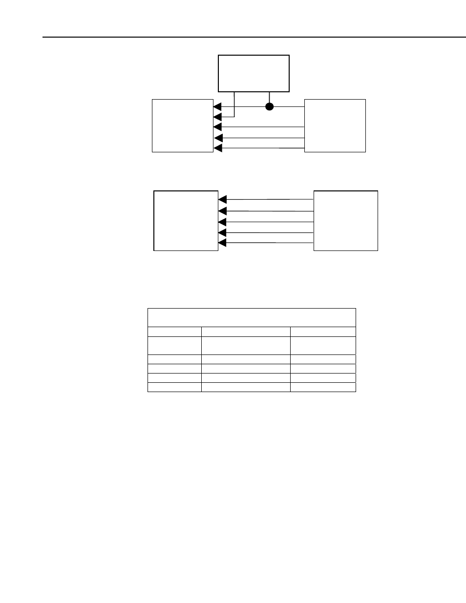
SDM-CD8S 8 Channel Solid State DC Control Module
EXTERNAL
8 TO 26 VDC
+ —
SDM-CD8S
DATALOGGER
GND
C1
C2
C3
Connection to External Supply
SDM-CD8S
DATALOGGER
12 V
C1
C2
C3
GND
Connection to Datalogger Supply
FIGURE 2. Connection block diagrams
TABLE 1. Datalogger to SDM-CD8S Connections
SDM-CD8S Datalogger
Function
PWR
12 V on datalogger or
8 to 26 V external supply
Power
Logic Gnd
Gnd
Common ground
C1
C1 (Control Port 1)
Data
C2
C2 (Control Port 2)
Clock
C3
C3 (Control Port 3)
Enable
4.1.2 Controlled Device Connections
In most applications, the SDM-CD8S acts as a switch (controllable break) in
the ground return of the circuit powering the controlled device. Figure 3
shows an example.
4