5 rs-232, Rs-232, 3. rs-232 pinout (9-pin d-sub female) – Campbell Scientific RF401A-Series Spread Spectrum Radios User Manual
Page 18
RF401A-Series Spread Spectrum Radio
4
RX
O
Serial data receive line
5
Modem Enable
I
Raised when datalogger determines
that associated modem raised the ring
line
6
Synchronous
Device Enable
I
Used by datalogger to address
synchronous devices; can be used as a
printer enable
7
CLK/Handshake
I/O
Used by datalogger with SDE and TX
lines to transfer data to synchronous
devices
8
12V supplied by
datalogger
PWR
Sources 12 Vdc to power peripherals
9
TX
I
Serial data transmit line
I = Signal into the RF401A series, O = Signal out of the RF401A series
7.5 RS-232
The RS-232 port is a DCE, 9-pin female D-Sub connector used to for
connecting the radio to the RS-232 port of a datalogger, computer, or another
RS-232 device. This connection is most commonly used when connecting the
radio to a device without a CS I/O port or when linking two communication
peripherals, for example directly connecting the radio to an Ethernet serial
server.
The RS-232 port can be connected to a DTE device, like a computer or NL201,
using the pn 10873, 9-Pin female to 9-Pin male serial cable. The RS-232 port
can be connected to another DCE device, like a datalogger RS-232 or MD485
or cellular modem, using the 18663 9-pin male-to-male null modem serial
cable.
When using RS-232, 12 Vdc power should be supplied to the power connector
using a field power connector or AC power adapter. The
Active Interface
setting must be set to
RS-232, and the RS-232 port configuration, like baud
rate, should match the device the radio is connected to.
RS-232 cannot be used for radio configuration using Device Configuration
Utility.
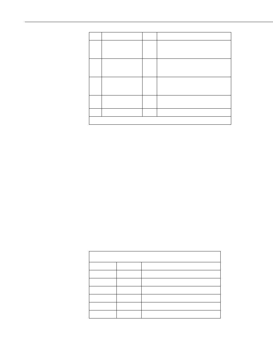
TABLE 7-3. RS-232 Pinout (9-PIN D-SUB FEMALE)
PIN
I/O
DESCRIPTION
1
2
O
TX
3
I
RX
4
5
GND
6
8