4 cs i/o, Cs i/o, 1. usb pinout (usb type b jack) – Campbell Scientific RF401A-Series Spread Spectrum Radios User Manual
Page 17: 2. cs i/o pinout ( 9-pin d-sub male)
RF401A-Series Spread Spectrum Radio
When the radio is connected to the PC, a virtual COM port will be added to the
list of available Ports (COM and LPT) devices. It will be descriptively labeled,
for example “RF401A Series (COM10)”, where COM10 denotes the COM
port enumerated by the Windows operating system.
The USB port is always available for configuration purposes. Independent of
the Active Interface radio setting, USB can always be used for connecting with
Device Configuration Utility for radio configuration.
The USB interface is only available for operational, network communication
when the radio’s
Active Interface setting is set as USB.
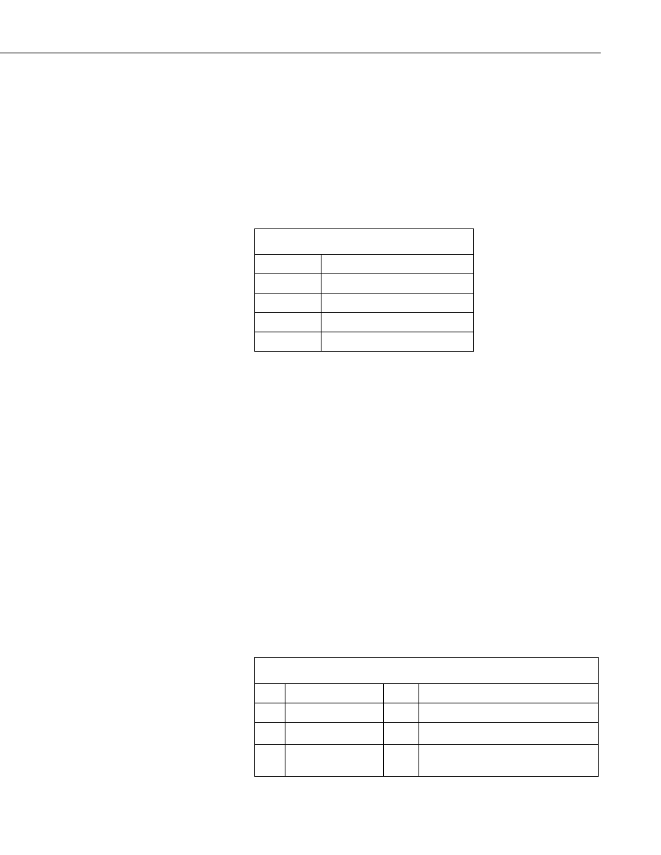
TABLE 7-1. USB Pinout (USB Type B Jack)
PIN
FUNCTION
1
5V
2
Data–
3
Data+
4
GND
7.4 CS I/O
The CS I/O port is a 9-pin male D-Sub connector that is typically connected to
a Campbell Scientific datalogger using the supplied SC12 cable. This
connection is used for power and data.
The CS I/O port is not a typical RS-232 connection and is specific to Campbell
Scientific products. CS I/O cannot be used for radio configuration using the
Device Configuration Utility.
For a typical remote radio site, the radio need only be connected to the
datalogger CS I/O port using the supplied SC12 cable. This connection will
supply operational power to the radio and serve as the data connection between
the radio the datalogger. The
Active Interface setting must be set to CS I/O
SDC.
An alternative, but much less common, use of CS I/O is connection to another
communication peripheral through an A100 CS I/O null modem adapter. This
is typically only used when creating a “phone to RF base” configuration. The
radio’s
Active Interface setting must be set to CS I/O ME Master and the
other device (for example COM220) must be capable of being configured as a
modem enabled (ME) peripheral.
TABLE 7-2. CS I/O Pinout ( 9-PIN D-SUB MALE)
PIN
FUNCTION
I/O
DESCRIPTION
1
5V
I
Sources 5 Vdc to power peripherals
2
GND
GND for pin 1 and signals
3
Ring
O
Raised by modem to put datalogger
into telecommunications mode
7