Campbell Scientific Kipp and Zonen CMP-Series Pyranometers User Manual
Page 19
CMP/CMA series manual
Page
18
4.9. Zero offset B
Proportionally to the ambient temperature the instrument temperature varies and causes heat currents
inside the instrument. This will cause an offset commonly called Zero Offset type B. It is quantified as
the response in W/m
2
to a 5 K/hr change in ambient temperature.
4.10. Operating
temperature
The operating temperature range of the radiometer is determined by the physical properties of the
individual parts. Within the specified temperature range Kipp & Zonen radiometers can be operated
safely. Outside this temperature range special precautions should be taken to prevent any physical
damage or performance loss of the radiometer. Please contact your distributor for further information
regarding operation in unusually harsh temperature conditions.
4.11.
Field of view
The field of view is defined as the unobstructed open viewing angle of the radiometer. ISO and WMO
require that a pyranometer for the measurement of global solar radiation has a field of view of 180
° in
all directions (i.e. a hemisphere). The inherent field of view of the instrument should not be confused
with the clear field of view of the installation location.
4.12. Directional
response
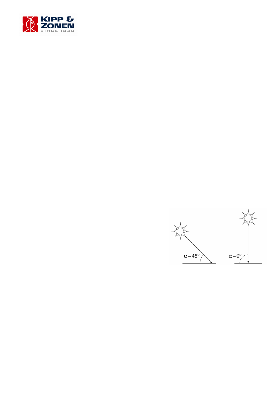
Radiation incident on a flat horizontal surface originating
from a point source with a defined zenith position will have
an intensity value proportional to the cosine of the zenith
angle of incidence. This is sometimes called the ‘cosine-
law’ or ‘cosine-response’ and is illustrated in figure 11.
Ideally a pyranometer has a directional response which is
exactly the same as the cosine-law. However, in a
pyranometer the directional response is influenced by the
quality, dimensions and construction of the domes. The
maximum deviation from the ideal cosine-response of the
pyranometer is given up to 80
° angle of incidence with
respect to 1000 W/m
2
irradiance at normal incidence (0
°).
Figure 11 Solar zenith angle
4.13. Maximum
irradiance
The maximum irradiance is defined as the total irradiance level beyond which physical damage may
occur to the instrument.