Operation – Campbell Scientific IRS21 Road Weather User Manual
Page 21
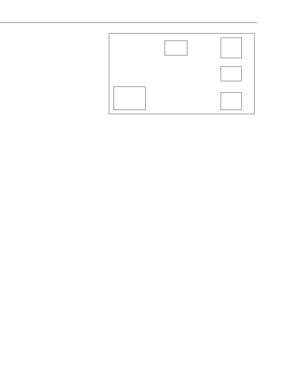
IRS21 Lufft Intelligent Road Surface Sensor
Input
connector
UB
RS232
connector
Output
connector
GND
Sensor Connector
DIP Switch
X
X
The interface has a two position dip switch that can change the interface from
master to slave operation. For operation with the RWIS station the interface is
set to master and each interface takes a port on the SDM-SIO4.
The switches in the two left hand positions as indicated by the X’s above make
the interface a master.
The sensors can be daisy chained. This is done by writing the address of the
sensor with software available only to the manufacturer at this time. The
sensor connections are made to the sensor connector.
The input connector and output connectors are used for daisy chain operation,
but are also used to supply the 12 volts to the interface and sensor.
In the figure above, power is applied to the input and output connectors.
12 volts is connected to the UB connection of the input connector from the
power buss. Ground is connected from the power buss to the GND connection
to the output connector.
5. Operation
The sensor is operated at two-minute intervals. This is done to prevent
measurement errors from sensor heating that could happen if the sensor were
powered too long. The sensor is polled with a command that asks for:
Temperature 1
Temperature 2
Temperature 3
Salt concentration
Freezing temperature
Water film height
Road condition
Error status
Sensors purchased for the Campbell Scientific RWIS station are not optioned
with the first two temperature sensors. For these applications, 107 probes are
used for sub surface temperature measurements. When these are used, one is
placed at the bottom of the saw cut near the sensor. The other 107 is placed
into the bottom of an 18” deep by 1/2” hole under the 107 probe placed into the
saw cut near the IRS21.
17