Campbell Scientific HydroSense® Soil Water Content System (CS620, CD620) User Manual
Page 11
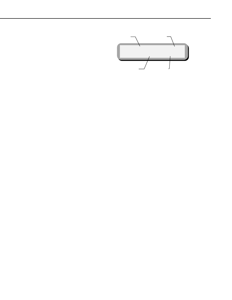
HydroSense Soil Water Measurement System (CD620, CS620)
RWC 33 Site 1
Deficit mm 34 20
Relative
Water
Content
Site
Currently
Selected
Deficit
12 cm Probe
Deficit
20 cm Probe
FIGURE 5-1. HydroSense display in Water Deficit Mode
5.3 Calibration—Setting the Lower and Upper Reference Levels
Lower and upper reference levels must be set to use the HydroSense in the
Water Deficit Mode. HydroSense measurements are used to set the reference
levels for a particular site. Once the reference levels are stored in the
HydroSense, further measurements provide a relative water content and a
water deficit value. The water deficit is the amount of water which must be
added to bring the soil water content to the upper reference level.
The water deficit calculation applies to a soil depth equal to the probe rod
length, i.e. 12 or 20 cm. Knowledge of the particular soil allows extrapolation
for other depths. For example, if the soil profile is known to be homogeneous
in the surface 30 cm, a water deficit calculation of 15 mm using 20 cm rods
can be multiplied by the ratio of extrapolated depth (30 cm) to rod length (20
cm) to give a corrected deficit value of 22.5 mm .
Figure 5-2 presents the button sequence to set the lower (0) and upper (100)
reference levels for any of 5 separate sites. The 0 and 100 values are stored in
memory by taking a HydroSense measurement in the soil which is at a water
content corresponding to the desired 0 and 100 values.
7