3 wiring, 1 datalogger connection, Wiring – Campbell Scientific CS106 Barometer User Manual
Page 16: Datalogger connection, 3. cs106 wiring diagram
CS106 Barometric Pressure Sensor
7.3 Wiring
7.3.1 Datalogger Connection
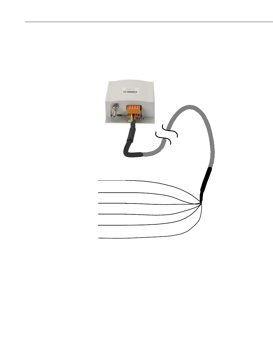
Before connecting the barometer to the datalogger, a yellow warning label
must be removed from the pigtails. The warning label reminds the user of the
importance of properly connecting the barometer to the datalogger. Wiring is
shown in FIGURE 7-3 and TABLE 7-1.
See Table 3-1 Blue – Pressure (VOUT)
See Table 3-1 Yellow – Signal Ground (AGND)
Continuous 12 VDC Red – 12 VDC (SUPPLY)
See Table 3-1 Black – Power Ground (GND)
Control Port or Excitation Channel Green – Control (EXT. TRIG)
Ground or Analog Ground Clear – Shield (G or AGND)
FIGURE 7-3. CS106 wiring diagram
See
See
Continuous 12 Vdc
See
Control Port or Excitation Channel
Ground or Analog Ground
8