Appendix b. cs i/o connection, B.1 cs i/o 9-pin connection – Campbell Scientific COM220 56k Phone Modem User Manual
Page 33
Appendix B. CS I/O Connection
B.1 CS I/O 9-Pin Connection
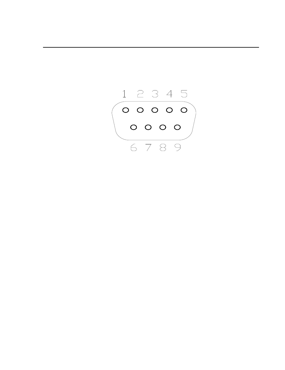
The pinout of the connector is shown in FIGURE B-1. The direction of the
signal relative to the modem is shown in parentheses. Unless specified
otherwise, all levels are 0 V for logic low, 5 V for logic high.
FIGURE B-1. CS I/O pinout
1. (input) +5 Vdc supply. Used to power internal line drivers for ‘Ring’ and
‘RX Data’ output signals.
2. (input) Ground
3. (output) Ring — A logic high signifies a ring signal has been detected.
4. (output) RX Data — Serial data from COM220
5. (input) Modem Enable — A logic high internally switches power to the
modem. A logic low internally shuts off power to the modem.
6. (input) Serial Device Enable — A logic high disables communication with
the modem without removing power or changing the modem's mode.
7. (input) SDC clock
8. (input) +12 Vdc supply
9. (input) TX Data — Serial data to COM220
B-1