3 #19520 cws900 connector – Campbell Scientific A150 Desiccated Case User Manual
Page 9
A150 Desiccated Case
WHITE
BLUE
GREEN
RED
BLACK
CLEAR
1
2
3
4
5
6
#22018
PWENC Connector
#26972 Cable
BLACK Signal Pulse
WHITE Signal Reference
CLEAR Shield
(Pin #)
Anemometer
FIGURE 6. Anemometer Wired to an A150
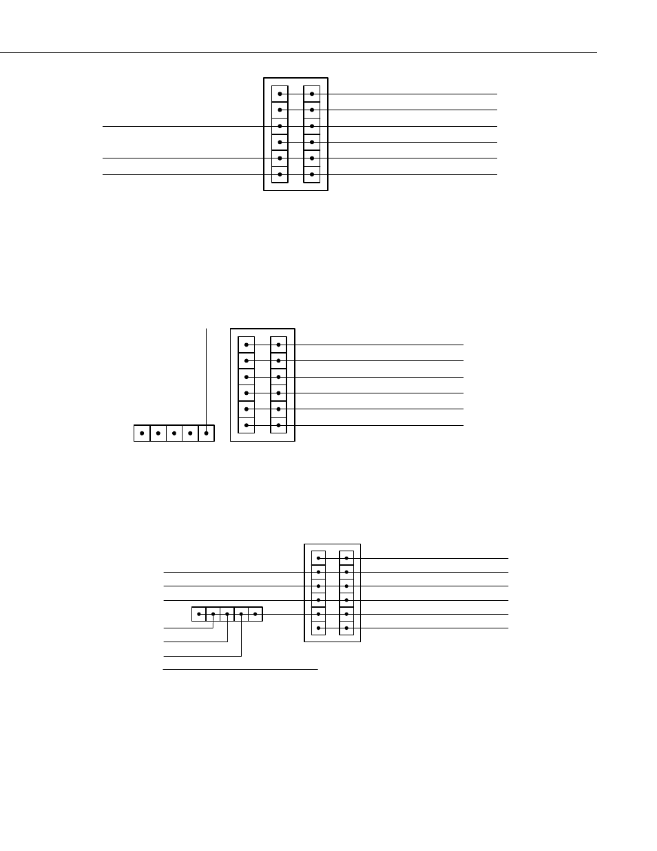
4.3 #19520 CWS900 Connector
Figure 7 shows the A150 terminal block with a CWS900 attached. This
configuration allows a CS450 or other sensor to be attached to the A150 while
the CWS900 wireless sensor interface completes the connection to the wireless
sensor network.
BL
A
C
K
#19520
CWS900 Connector
BLUE
RED
CLEAR
GREEN
1
2
BLACK
3
4
WHITE
5
6
(Pin #)
#26972 Cable
FIGURE 7. A150 with CWS900 Connector
Figure 8 shows a CS450 connected to an A150. Note how multiple grounds
are combined into a single lead wire using the lever nut.
BLUE
RED
CLEAR
GREEN
1
2
BLACK
3
4
WHITE
5
6
BLACK
#19520
CWS900 Connector
#26972 Cable
WHITE
BLUE
BLACK
YELLOW
CLEAR
RED
TUBE
N.C.
N.C.
Terminates in A150 Enclosure
A150
Pressure Sensor
CS450
Sensor TX (Out)
Sensor RX (In)
Power GND
Digital GND
Shield
Power
Vent
(Pin #)
FIGURE 8. A150 Wired for CS450 Pressure Sensor and CWS900 Connector
5
- 014A Met One Wind Speed Sensor (36 pages)
- 020C Wind Direction Sensor (26 pages)
- 024A-L Met One Wind Direction Sensor (30 pages)
- 03001-L R.M. Young Wind Sentry Set (34 pages)
- 03002, 03101, and 03301 R. M. Young Wind Sentry Sensors (40 pages)
- 034A-L WindSet (16 pages)
- 034B-L Met One Windset (34 pages)
- 036, 038 Spark Gapped Junction Box (6 pages)
- 05103, 05103-45, 05106, and 05305 R. M. Young Wind Monitors (30 pages)
- 083E Relative Humidity and Temperature Sensor (22 pages)
- 0871LH1 Freezing Rain Sensor (31 pages)
- 092 Barometric Pressure Sensor (24 pages)
- 10164-L Water Sampler Control Cable for use with Isco and Sigma Autosamplers (18 pages)
- 107-L Temperature Probe (28 pages)
- 108-LC Temperature Probe for MetData1 (12 pages)
- 108-L Temperature Probe (30 pages)
- 109-L Temperature Probe (30 pages)
- 109SS Temperature Probe (32 pages)
- 110PV Surface Temperature Probe (32 pages)
- 21108 RF450 Demo Kit (14 pages)
- 223-L Delmhorst Cylindrical Soil Moisture Block (28 pages)
- 227-L Delmhorst Cylindrical Soil Moisture Block (24 pages)
- 229 Water Matric Potential Sensor and CE4/CE8 (34 pages)
- 237-L Leaf Wetness Sensor (14 pages)
- 247-L Conductivity and Temperature (18 pages)
- 253-L and 257-L (Watermark 200) Soil Matric Potential Sensors (36 pages)
- 25458 DIN-Rail Terminal Kit (10 pages)
- 255-100 Novalynx Analog Output Evaporation Gauge (16 pages)
- 260-953 Alter-Type Wind Screen for Tipping Bucket Rain Gages (14 pages)
- 27106T Gill Propeller Anemometer (18 pages)
- 30066 Battery Terminal Bus (1 page)
- 380, 385, 380M, 385M Met One Rain Gages (22 pages)
- 3WHB10K 3-Wire Half-Bridge Terminal Input Module (14 pages)
- 43347 RTD Temperature Probe and 43502 Aspirated Radiation Shield (40 pages)
- 4386 Battery Terminal Bus (1 page)
- 4WFB120, 4WFB350, 4WFB1K 4-Wire Full Bridge Terminal Input Module (22 pages)
- 4WFBS120, 4WFBS350, 4WFBS1K 4 Wire Full Bridge Terminal Input Modules (46 pages)
- 4WPB100, 4WPB1K PRT Terminal Input Modules (16 pages)
- 52202 Electrically Heated Rain and Snow Gage (16 pages)
- 9522B Iridium Satellite Modem and COM9522B Interface Modem (46 pages)
- A100LK Anemometer (18 pages)
- A21REL-12 Relay Driver (10 pages)
- A6REL-12 Relay Driver (12 pages)
- AL200 ALERT2 Encoder, Modulator, and Sensor Interface (44 pages)