Physical description – Campbell Scientific A150 Desiccated Case User Manual
Page 6
A150 Desiccated Case
It is not recommended to insert more than one wire into each
connection on the terminal block. If it is necessary to combine
wires, use the 5-position lever nut to combine the wires, and then
insert the lead wire from the lever nut into the terminal block.
NOTE
When used with a CWS900, the sensor can be used with sensors measuring
analog voltages, frequency, and pulse. The CWS900 can also provide
excitation voltage to a sensor through the A150.
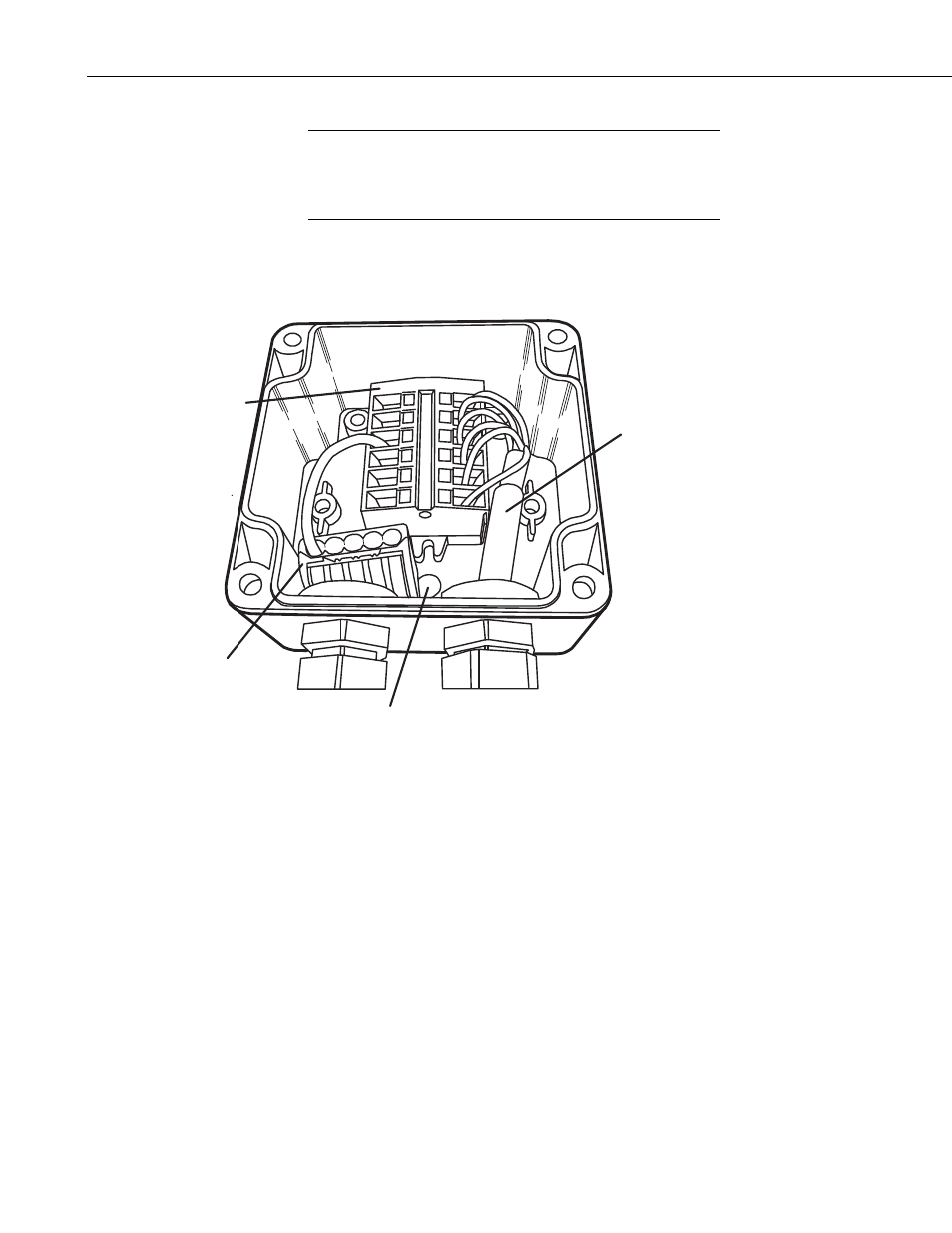
Terminal Block
Lever Nut
Wire to Datalogger
or CWS900
Vent
FIGURE 2. A150 Interior
2. Physical Description
The A150 has an 80 mm x 82 mm x 55 mm chassis. Four screws secure the lid
to the rest of the unit. A terminal block is mounted inside the chassis. A small
vent is located on the bottom of the chassis. The vent is protected by a GORE
®
filter, which prevents moisture and contaminants from entering the unit while
equalizing the interior air pressure to the current atmospheric pressure.
A mounting bracket is attached to the bottom of the chassis. The bracket is
used to fasten the A150 inside an enclosure or, with the included Velcro
®
strap,
to another location of the user’s choosing.
2