2 #22018 pwenc connector – Campbell Scientific A150 Desiccated Case User Manual
Page 8
A150 Desiccated Case
4.1 #26972 with Stripped and Tinned Continuation Cable
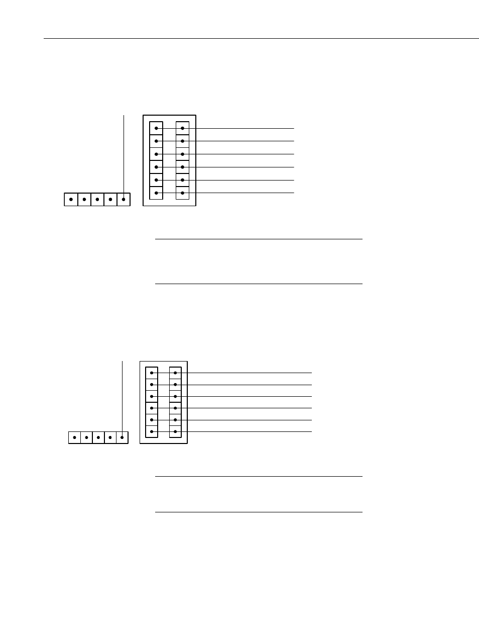
Figure 4 shows the A150 terminal block with a 26972 continuation wire
attached. This configuration allows a CS450 or other sensor to be attached to
the A150 while the pigtail wire completes the connection to the datalogger.
WHITE
BLUE
GREEN
RED
BLACK
CLEAR
BL
A
C
K
#26972 Cable w/ Tinned Wire Ends
FIGURE 4. A150 with Continuation Cable
Wire colors may vary between different sensors. It is up to the
installer to take into account any mismatched wire colors
between the sensor and pigtail wire when connecting wires to the
A150.
NOTE
4.2 #22018 PWENC Connector
Figure 5 shows the A150 terminal block with a PWENC connector attached.
This configuration allows a CS450 or other sensor to be attached to the A150
while the PWENC connector completes the connection to a pre-wired
enclosure.
WHITE
BLUE
GREEN
RED
BLACK
CLEAR
1
2
3
4
5
6
BL
A
C
K
#22018
PWENC Connector
(Pin #)
#26972 Cable
FIGURE 5. A150 with PWENC Connector
When using the A150 to wire a sensor to a PWENC connector,
ensure the wiring inside the pre-wired enclosure corresponds
with the wiring from the sensor.
NOTE
Figure 6 gives an example of an anemometer wired to an A150. Note that the
green wire in the PWENC connector must be connected to a datalogger’s pulse
input inside the enclosure for the signal to be measured.
4