Programming examples – Campbell Scientific 4WPB100, 4WPB1K PRT Terminal Input Modules User Manual
Page 7
4WPB100, 4WPB1K PRT Bridge Terminal Input Modules
3
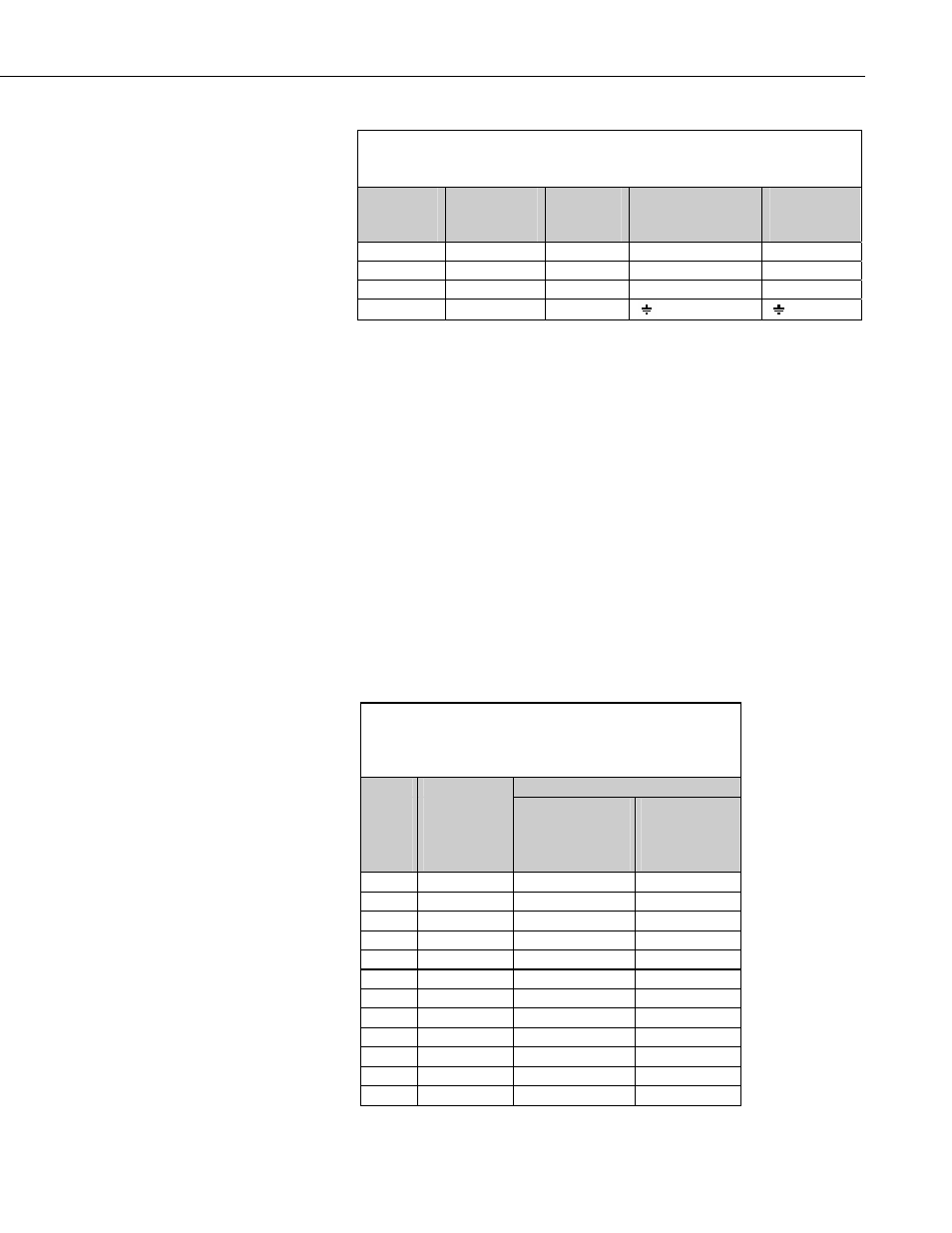
TABLE 3-1. 4WPB100/4WPB1K Connections to
Campbell Scientific Dataloggers
Function
Label/Lead
CR10X,
CR510
CR23X, CR1000,
CR800, CR850,
CR3000
21X, CR7,
CR9000X
Excitation
Black Wire
E1
EX1
Excitation 1
V1 High
H
1H
1H
1H
V1 Low
L
1L
1L
1L
Ground G
AG
4. Programming Examples
The following examples simply show the two instructions necessary to 1)
make the measurement and 2) calculate the temperature. The result of the 4
wire half bridge measurement as shown is Rs/Ro, the input required for the
PRT algorithm to calculate temperature. Note that “Full Bridge” is shown as
the name for measurement Instruction 9 (used with CR10(X), 21X, and CR7).
When Instruction 9 is used with the first measurement range not set to the
maximum input range, it becomes a four wire half bridge measurement.
All the examples are for a 100 Ohm PRT in the 4WPB100. The excitation
voltages used were chosen with the assumption that the temperature would not
exceed 50 °C. Tables 4-1 and 4-2 list excitation voltage as a function of
maximum temperature and the input voltage ranges used with the different
dataloggers. Calculation of optimum excitation voltage is discussed in Section
5.1.
TABLE 4-1. Excitation Voltage for 100 Ohm PRT in
4WPB100 Based on Maximum Temperature and Input
Voltage Range
Excitation Voltage, mV
Max.
Temp
°C
PRT
Resistance
Ohms
±25 mV Input
Range, CR10(X),
CR800, CR850,
CR1000
±50 mV
Range, 21X,
CR7, CR3000,
CR9000X
50 119.4
2035
4070
100 138.5
1758
3516
150 157.31
1551
3101
200 175.84
1390
2780
250 194.07
1262
2523
300 212.02
1157
2314
350 229.67
1070
2140
400 247.04
997
1993
450 264.11
934
1867
500 280.9
879
1759
550 297.39
832
1664
600 313.59
790
1581