ACR Electronics 2662 User Manual
Page 10
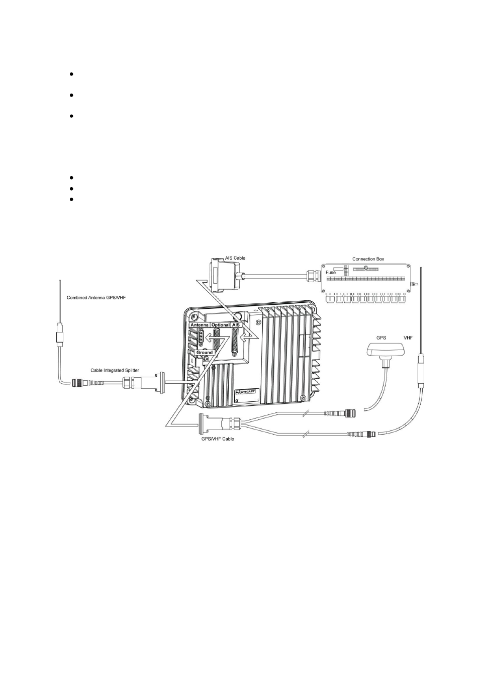
Step-by-Step Installation Procedure:
Mount the NAUTICAST
™ close to ships operation workstation for traffic surveillance
and maneuvering.
Use the VHF adapter cable (P/N 2612) together with the VHF plug and TNC plug to
connect the VHF and GPS antenna cables and antennas.
The sensors, ECDIS, PC, pilot case, long range devices and auxiliary displays can be
connected to the NAUTICAST
™ cabinet by the AIS cable by means of the connection
box. The device is driven by a 24V DC 7A supply, which is connected to the power
terminal at the connection box. The AIS should be connected to an emergency power
source. A battery capacity calculation together with GMDSS-equipment is needed!
Please refer to Appendix 9.1 for examples of battery capacity calculations.
After performing these steps, the NAUTICAST
™ automatically starts operation.
The NAUTICAST
™ has a ground terminal which has to be connected to ship ground.
Now configure the required initial system parameters a
ccording to Chapter 4 “Starting
the NAUTICAST
™.”
NAUTICAST
Connection Diagram
Note: The optional ACR connection box includes a fuse of 6,3A. If it is not used, then the unit
has to be protected against high current by an external slow blow fuse of 6,3A.
6
Y1-03-0212H