3 permitted speed of rotation, 2 determining the permitted speed of rotation, Important – ROHM KFD-N - Draw-down power chucks User Manual
Page 13: N] (4), N] (5), Mkg] (6), Mkg] (7) m, Mkg] (8) f, 30 p
13
R
a
max. in mm
63
78
106
135
185
250
335
9.3 Permitted speed of rotation
The following formula applies for determining the
permitted speed of rotation for a specific machi-
ning job:
n
perm
=
[min
–1
] (9)
(Nothe the number of jaws for
S M
c.
)
.
n
9.2.1 Centrifugal force F
c
, and centrifugal moment M
c
Formulae (1), (2) and (3) produce the following result
for clamping from the outside in:
F
sp
= – F
c
[N]
(4)
In this case the centrifugal force F
c
is dependent on
the mass of all jaws m
B
, the centre of gravity radius r
s
and the speed of rotation n.
The following formula can be derived:
F
c
= (m
B
.
r
s
)
.
( )
[N]
(5)
The expression m
B
⋅
r
s
is called the centrifugal
moment M
c
M
c
= m
B
.
r
s
[mkg]
(6)
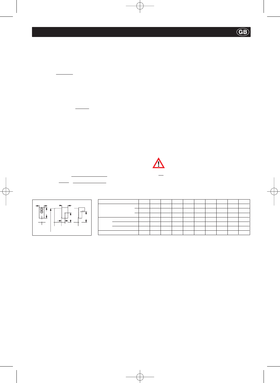
The following formula applies to chucks with sliding
and false jaws in which the false jaws AB can be mo-
ved in order to alter the clamping area and the sliding
jaws GB approximately maintain their radial position:
M
c
= M
cGB
+ M
cAB
[mkg]
(7)
M
cGB
can be obtained from the table below.
M
cAB
can be calculated using the following formula:
M
cAB
= m
AB
⋅
r
sAB
[mkg]
(8)
F
spo
S
sp
p
30
30
p
Do not exceed the maximum speed of rotation
n
max
of the chuck (marked on the body of the
chuck). This applies even if the calculated
permitted speed of rotation n
perm
is greater than
the maximum speed n
max
.
9.2 Determining the permitted speed of rotation
2
B
A
Chuck
C
o/
L
A
R
A
r
s
Important:
Ǹ
F
spo
– (F
spz
.
S
z
)
M
c
ȍ
A
75
95
103
130
130
130
130
Max. weight in kg
0,88
1,4
2,58
3,1
3,1
3,1
3,1
Chuck size
220
280
350
400
500
630
800
at max.
speed
B
36,5
45
50
50
50
50
50
C
53
54.5
80
80
80
80
80
L
a
max. in mm
29
30
45
45
45
45
45
Centrifugal moment M
C
GB [mkg]
0,070
0,161
0,400
0,718
1,17
2,94
4,95
09241-k001-001 29.04.2004 14:52 Uhr Seite 13