Pc wiring display module w iring – Matrix Orbital GLK24064-25 Legacy User Manual
Page 9
GLK24064-25 rev. 06
9
PC wiring
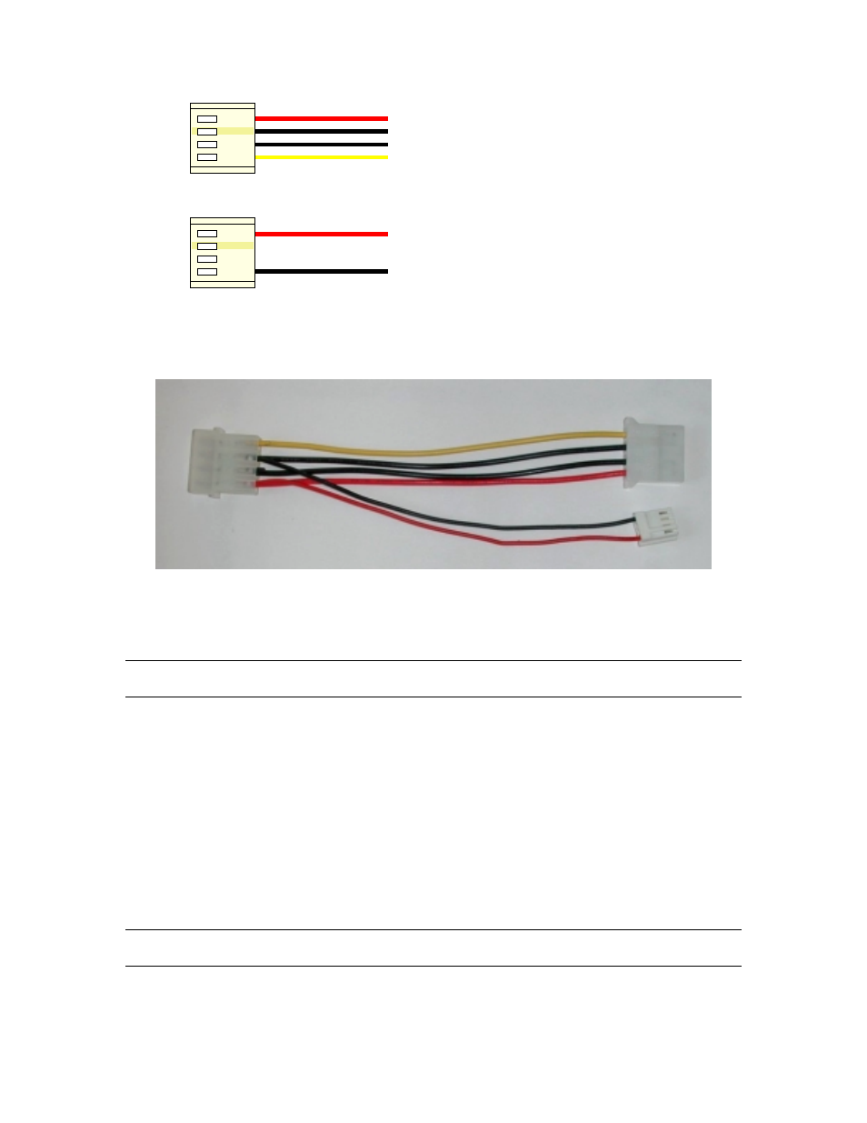
Display module w iring
+5 V
+5 V
GND
GND
+12 V
Figure 2-2 Wiring for 5 volt modules
If you don't want to modify cable wiring yourself, Matrix Orbital can supply an adapter cable designed to
use with the display module when it's installed in a PC. The cable is wired as shown in Figure 2-3 below.
Figure 2-3 Five volt Power Cable
Simply insert the splitter cable in series with a "large" power connector (e.g. one going to a hard drive) and
plug the small connector into the display module. The connector is 'keyed' and will only fit one way.
Note: The connector provided does not allow access to the middle two pins, which are used for I
2
C
communications. If you need this functionality, we suggest you wire a suitable connector.
2.1.2 Wide Voltage with Efficient Switching Power Supply (VPT)
Power is applied to the white or brown four pin SIP connector as follows:
Pin 1: +8 - 30V DC
Pin 2: = SCL (I²C clock)
Pin 3: = SDA (I²C data)
Pin 4: Gnd
If the sole data source is via RS - 232, the data input is via the DB9 connector. In this case pins 2 and 3 are
not used.
2.1.2.1 Twelve volt Power Cable
Note: Do not use this cable unless your display module has the "wide voltage range" option (option V). Use
of the 12 volt power cable with 5 volt modules will damage the module.
The 12 volt power cable is designed for use with wide voltage range display modules mounted in a PC.
Wiring required for the 12 volt power connector is shown in Figure 2-4 below.