Connections, 1 power, Warning – Matrix Orbital GLK24064-25 Legacy User Manual
Page 8: Do not apply any power with reversed polarization
GLK24064-25 rev. 06
8
2. Connections
2.1 Power
Warning:
!
Do not apply any power with reversed polarization.
!
Do not apply any voltage other than the specified voltage.
!
Do not use any cables other than the cables supplied by Matrix Orbital,
unless you are aware of the modifications required.
!
Do not under any circumstances use an unmodified floppy drive power
cable.
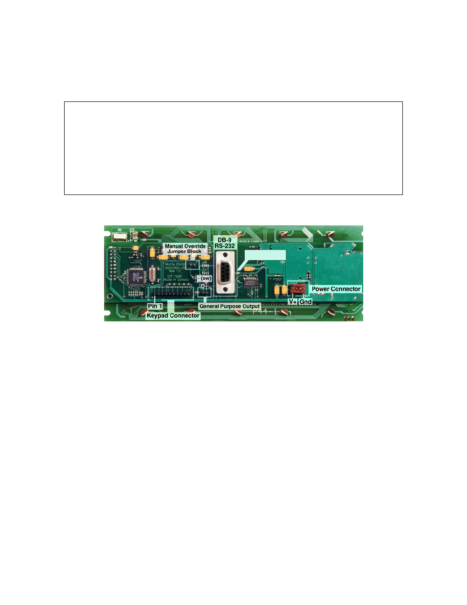
Refer to the diagram below for this chapter.
5V j umper
Figure 2-1 Electrical Connections
2.1.1 Regular Voltage
Power is applied to the white or brown four pin SIP connector as follows:
Pin 1: +5V DC ± 0.25V
Pin 2: = SCL (I²C clock)
Pin 3: = SDA (I²C data)
Pin 4: Gnd
If the sole data source is via RS - 232, the data input is via the DB9 connector. In this case pins 2 and 3 are
not used.
2.1.1.1 Five volt Power Cable
If a GLK24064-25 module is used in a PC it is tempting to plug a spare power connector into the unit.
Don't do this! Wiring for the PC power connector and that required for the module are different as shown
in Figure 2-2 below.