Ashcroft D400 - Differential Pressure Switches User Manual
Page 2
INSTALLATION
These controls are precision instruments and should never be
left with internal components exposed. After installation, ensure
that the covers are in place and the conduit openings are closed.
MOUNTING 0400 AND 0700 SERIES
There are three holes external to the enclosure for surface
mounting. The locations of these holes are shown on the general
dimension drawing. The controls may also be mounted directly
on the pressure line using the pressure connection. When tight-
ening the control to the pressure line, always use the wrench
flats or the hex on the lower housing.
For operation as a pressure control, connect the pressure
source to the lower port marked “H.” If venting is required, con-
nect the vent line to the side port marked “L.” If no venting is
required, side port “L” must be left open.
For operation as a differential pressure control, connect the
high pressure source to the lower port marked “H” and connect
the low pressure source to the side port marked “L.”
ELECTRICAL CONNECTIONS
Remove Cover
D400 Series – two screws hold cover to enclosure
D700 Series – cover unscrews
CONDUIT CONNECTIONS
Note – It is recommended that Teflon tape or other sealant be
used on the conduit, bushing, or plug threads to ensure the
integrity of the enclosure.
D400 Series Standard – one
3
⁄
4
NPT conduit hole right side.
D700 Series Standard – two
3
⁄
4
NPT conduit holes with one
permanent plug. NEMA7 and 9 enclosures require proper con-
duit seals and breathers as per the National Electrical Code.
D400 and D700 Series – XJL variation – two
3
⁄
4
NPT conduit
holes with two
3
⁄
4
to
1
⁄
2
NPT reducing bushings.
D400 Series – XJK variation – two
3
⁄
4
NPT conduit holes.
D400 SERIES
SPDT – Wire directly to the switch according to circuit require-
ments. On controls with pilot lights, wire lights according to
circuit diagram on the inside of the cover. See special wiring
instruction tag for single switches with two pilot lights and dual
switches with one or more pilot lights.
2-SPDT – Dual switching elements consist of two SPDT switches
mounted together in a bracket. The switches are calibrated to
have simultaneous operation within 1% of range either on
increasing or on decreasing pressure, but not in both directions.
Wire directly to the front and rear switches according to circuit
requirements. Leads provided on the rear switch and leads
provided for hermetically sealed switch elements are color
coded as follows:
Common
– White
Normally Closed
– Red
Normally Open
– Blue
See SPDT instructions for pilot light hook up.
Installation and Maintenance Instructions for
D400 & D700 ASHCROFT
®
Snap Action Switches
for Low Range Differential Pressure Control
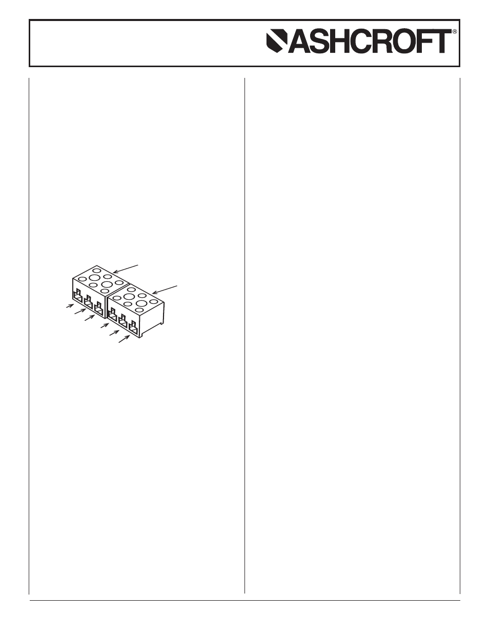
TERMINAL BLOCK
SWITCH A
TERMINAL BLOCK
SWITCH B
2
1
3
2
1
3
NC
NO
C
NC
NO
C
© 2007 Ashcroft Inc., 250 East Main Street, Stratford, CT 06614-5145, USA, Tel: 203-378-8281, Fax: 203-385-0499, www.ashcroft.com
All sales subject to standard terms and conditions of sale. I&M009-10009-10/00 (250-2289E) AMR 12/07
D700 SERIES
SPDT – Wire directly to the switch according to circuit requirements.
2-SPDT – Wire to front switch terminal block (left) and rear
switch terminal block (right) as marked. Strip insulation
5
⁄
16
˝,
insert in proper terminal connector, and tighten clamping screw
to secure.
D400 AND D700 SERIES
Adjustment of Setpoint – A Single setpoint adjustment nut
(
7
⁄
8
˝) is located centrally at the bottom on the inside of the
enclosure. The direction of turning is indicated on a label affixed
to the inside of the control enclosure. XG5 controls have a set-
point indication scale adjacent to the adjustment nut. To adjust
the control, align the top of the adjustment nut hex with the indi-
cator line on the scale. Do no force adjustment or attempt to
exceed the maximum setting shown on the scale or nameplate.
For accurate setpoint calibration or for controls without a
scale mount the control on a calibration stand so that the HIGH
and LOW pressures expected under operating conditions may
be obtained. Suitable reference standards are necessary for
each pressure.
Note – Due to the sensitivity of these controls it Is imperative
that the LOW pressure side volume be large to prevent a set-
point shift between calibration and field installation. If this is not
possible, an approximate setpoint under operating conditions
can be obtained by setting the operating point with the low side
open to atmosphere. A final setpoint adjustment can be made
after installation.
Apply the LOW pressure. Then apply the HIGH pressure to
the required setpoint and turn the adjustment nut until the
switch operates. When the setpoint has been achieved, raise
and lower HIGH pressure to ensure that the differential pres-
sure between the HIGH and LOW pressures is correct.
After installation of the control, replace the cover to ensure
electrical safety and to protect the internal parts from the
environment.
D400 AND D700 VARIABLE DEADBAND SWITCHES
Deadband is varied by rotating the wheel on the precision
switch. When viewed from the front of the enclosure, rotation to
the left increases deadband and rotation to the right decreases
deadband. The letters on the wheel may be used as a refer-
ence. Deadbands obtainable will vary from 2% to 9% of the
pressure range depending on the range segment and the type
of diaphragm.
Adjustment of Setpoint – As received, the pressure switch
wiIl normally be set to approximately 90% of range. Rotate the
wheel on the MICRO SWITCH all the way to the right. This will
provide the smallest deadband. Pressurize the system to the
required setpoint and turn the adjustment nut until the switch
changes mode. Lower the pressure to reset the switch. Rotate
the wheel on the MICRO SWITCH until the desired deadband
is obtained. The upper setpoint will be changing upward with
this adjustment. Lower the pressure to reset the switch.
Increase the pressure to the desired setpoint and turn the
adjusting nut until the switch changes mode. Lower the pres-
sure and check the re-setpoint and dead band.
Note – As indicated above, adjustment of setpoint is made by
use of the
7
⁄
8
˝ nut. The precision switch element mounting
screws and bracket adjusting screw are factory sealed and
should not be tampered with.