Ashcroft P-N7 pressure switches User Manual
Page 2
CONDUIT CONNECTIONS
Two
3
⁄
4
NPT holes are provided, one fitted with a plug, the other
with a cap. It is recommended that Teflon tape or other sealant
be used on conduit bushing or plug threads to ensure integrity
of the enclosure. NEMA 7 & 9 enclosures require proper conduit
seals and breathers as per the National Electrical Code.
SETPOINT ADJUSTMENTS
Series PP-S Single Switch – Remove front cover, held in place
by two screws. For setpoint adjustment to within + 1% of nomi-
nal range, use a suitable reference such as an Ashcroft
Duragauge or test gauge. Monitor switch with a suitable pilot
light or meter. Pressurize the system to the required setpoint
and turn the adjusting wheel until the switch changes mode.
When the setpoint has been achieved, raise and lower the pres-
sure to insure that the setpoint is correct.
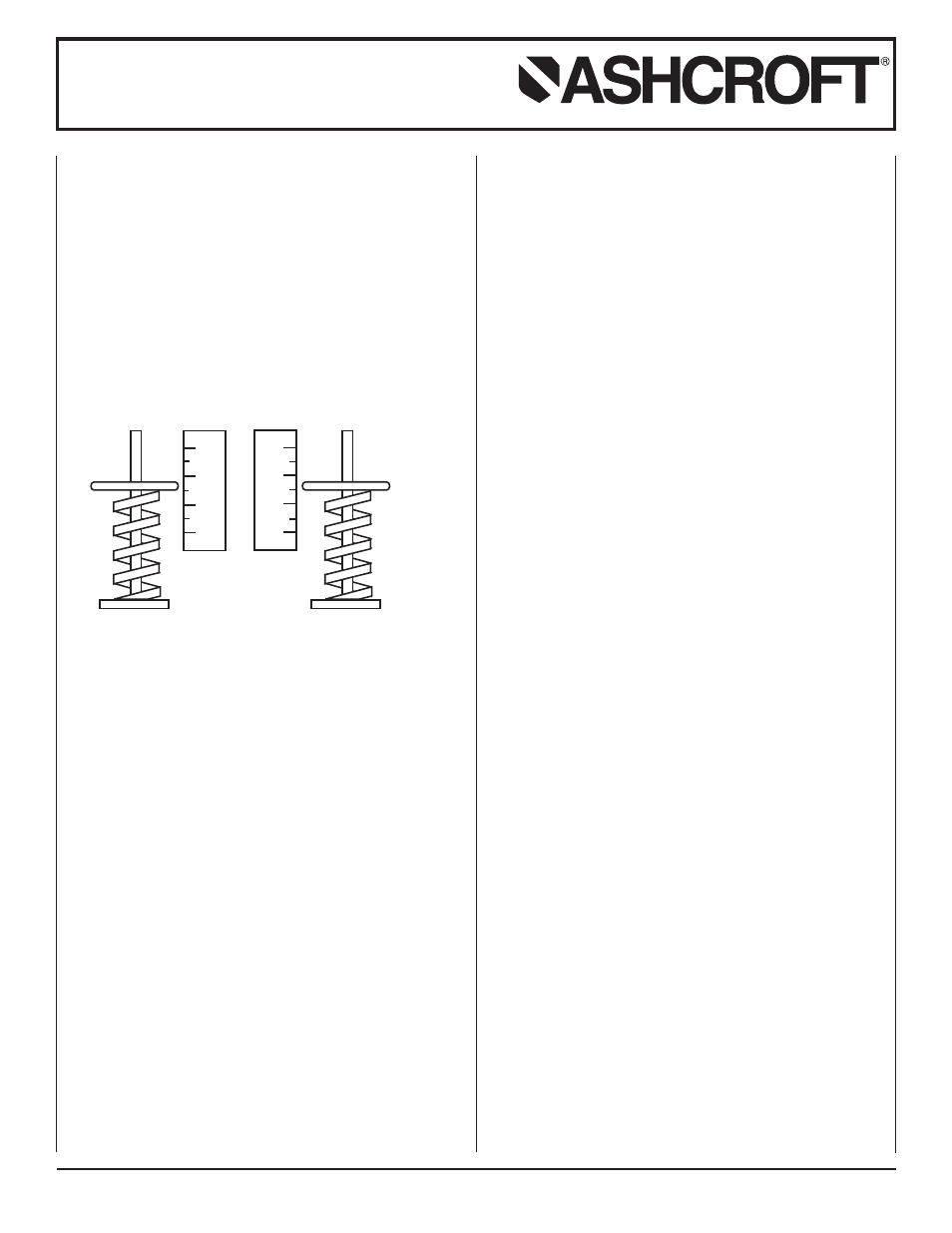
Series PP-D Dual Switch – Remove front cover, held in place
by two screws. There are two range adjusting wheels. The
adjusting wheel on the left (labeled A) controls the left switch,
the adjusting wheel on the right (labeled B) controls the right
switch. The switches are set independently.
NOTE: The units are calibrated at the factory such that for proper
operation switch B setpoint must be set higher than
switch A setpoint.
For setpoint adjustment to within ±1% of nominal range mount
the switch on a calibration stand, and use a suitable reference
such as an Ashcroft Duragauge or test gauge. Monitor switch
with a suitable pilot light or meter.
Pressurize the system to the required setpoint and turn the
adjusting wheel until the switch changes mode. When the set-
point has been achieved, raise and lower the pressure to insure
that the setpoint is correct. This must be done for both setpoint
A and setpoint B.
Series PP-A Adjustable Deadband SwItch – Remove front
cover, held in place by two screws. The adjusting wheel labeled
A controls the resetpoint of the switch. The adjusting wheel
labeled B controls the setpoint of the switch.
Note: The units are calibrated at the factory such that for proper
operation setpoint B is always higher than resetpoint A.
For accurate setpoint adjustment, mount the switch on a calibra-
tion stand, and use a suitable reference such as an Ashcroft
Duragauge or Test Gauge. Monitor switch with a suitable pilot
light or meter. Pressurize the system to the required setpoint.
Move adjusting wheel on spring B until switch changes mode.
Then lower pressure to the resetpoint, move adjusting wheel on
spring A until the switch changes mode. Raise and lower pres-
sure to insure that setpoint is correct. Repeat as necessary.
Installation and Maintenance Instructions for
ASHCROFT
®
High Pressure P-Series
Snap Action Switches with Buna N, Viton and
Teflon Diaphragms for Pressure Control
© 2014 Ashcroft Inc., 250 East Main Street, Stratford, CT 06614-5145, USA, Tel: 203-378-8281, Fax: 203-385-0499, www.ashcroft.com
All sales subject to standard terms and conditions of sale. I&M009-10212 P Series 03/2014
A
B
0
20
40
60
0
20
40
60
CAUTIONS TO OBSERVE
Switch Applications On Continuous Static Pressure:
Pressure switches that contain BUNA, VITON or TEFLON
diaphragms can experience some amount of compression set of
the diaphragm in high static pressure applications. This compres-
sion set has the potential to shift the switch setpoint while in ser-
vice. The setpoint can shift by approximately 2% (typically less
than 1%) from the original setting. To assure optimal long term
setting accuracy, Ashcroft recommends the switch setting be
checked after 30 Days in service and reset if necessary. As with
any calibrated instrument, Ashcroft recommends regular inspec-
tion of operation and setpoint setting.