Warning, Required for a given loop resistance (r – Ashcroft NPI pressure switches User Manual
Page 2
As received, the pressure switch will normally be set to
approximately 90% of the indicated range. Pressurize the sys-
tem to the required setpoint and turn the adjustment poten-
tiometer until the switch changes mode. Clockwise rotation of
the potentiometer will increase the setpoint and counter-clock-
wise rotation of the potentiometer will decrease the setpoint.
When the setpoint has been achieved, raise and lower the
pressure to ensure that the setpoint is correct.
The indicating LEDs will show red when the pressure is below
the setpoint and green when the pressure is above the setpoint.
For N4 XEA Switches Only – The setpoint is adjusted by a
ten turn potentiometer located externally on the top right of the
case. The setpoint is adjusted as above.
Adjustment of Deadband – A four turn adjustment poten-
tiometer is located at the upper right corner on the inside of the
enclosure just below the setpoint potentiometer.
The deadband is adjusted as above. Clockwise rotation of the
potentiometer will increase the deadband and counter-clock-
wise rotation of the potentiometer will decrease the deadband.
After installation of the control replace cover to protect inter-
nal parts from the environment.
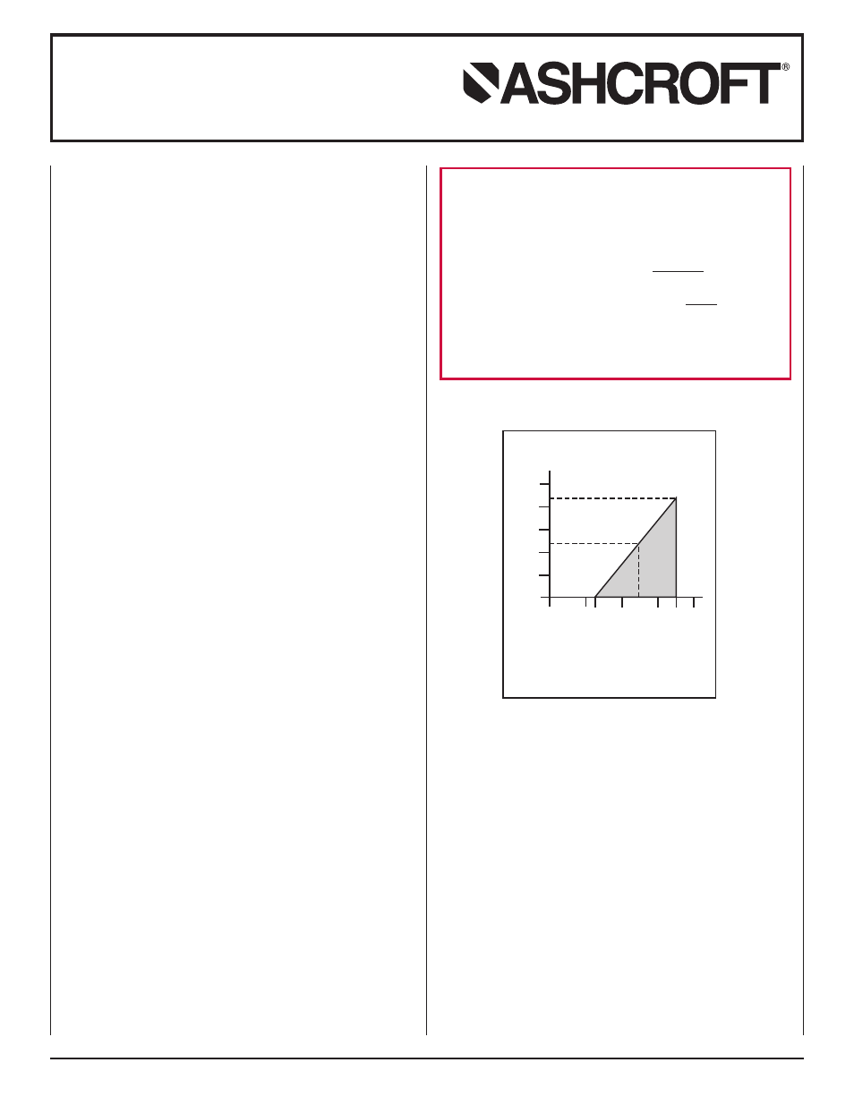
POWER SUPPLY – N4 & N7 SERIES 4-20mA OPTION
The maximum supply voltage for a 4-20mA current output
transducer is 36 dc while the minimum supply voltage is
dependent upon the loop resistance of the circuit. The load
limitation chart shows the minimum supply voltage (V
min
)
required for a given loop resistance (R
LOOP
).
NOISE
For minimum noise susceptibility, avoid running the transducer’s
cable in a conduit that contains high current AC power cables.
Where possible avoid running the cable near inductive equipment.
ADJUSTMENT POTENTIOMETERS
The zero and span pots are accessible through the front when
the cover is off. Remove the cover carefully. The zero and span
pots are labeled. For additional conduit hole on N4 Series,
order option (XJL).
Installation and Maintenance Instructions
for N Series Electronic Pressure Switch
LOOP SUPPLY VOLTAGE (VDC)
V
min
= 12V+ [.022A*(R
L
)]
*includes a 10% safety factor
R
L
= R
S
+ R
W
R
L
= Loop Resistance (ohms)
R
S
= Sense Resistance (ohms)
R
W
= Wire Resistance (ohms)
Load Limitations 4-20mA Output
Loop Resistance (Ω
Ω)
0
10 12
20
30
36
40
1250
1091
1000
750
500
250
0
545
24
OPERATING
REGION
WARNING!
This instrument is susceptible to damage when exposed
to static electrical charges. To avoid damage observe the
following:
• Ground the body of the instrument BEFORE making any
electrical connections
• When disconnecting, remove the ground LAST.
CAUTION: Pressure spikes in excess of the rated overpres-
sure capability of the instrument may cause irreversible elec-
trical and/or mechanical damage to the pressure measuring
and containing element(s).
© 2007 Ashcroft Inc., 250 East Main Street, Stratford, CT 06614-5145, USA, Tel: 203-378-8281, Fax: 203-385-0499, www.ashcroft.com
All sales subject to standard terms and conditions of sale
. I&M009-10026-6/04 (250-B145-01) Rev. 3 AMR 05/10