Ashcroft GL42 - Low Differential Indicating Pressure Transmitter User Manual
Page 2
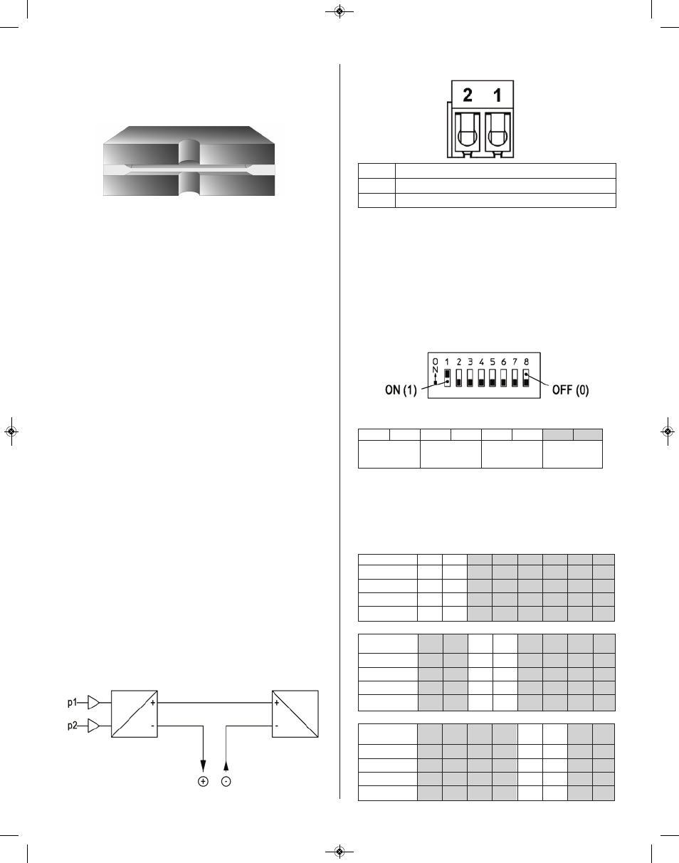
b. Design and mode of operation
The transmitter is based on a capacitance sensor element
with a micro machined differential capacitor using a patented
silicon-on-glass technology. This ultra-thin single crystal dia-
phragm provides excellent sensor repeatability and stability.
Sensor cross section
The silicon diaphragm sensor has no glues or other organics
to contribute a drift or mechanical degradation over time.
12. INSTALLATION AND ASSEMBLY
All supply lines should be arranged so that there are no me-
chanical forces acting on the device.
The GL42 is calibrated for vertical installation; however any
installation position is possible. If an installation position
other than vertical is selected, the zero-point signal can be
corrected as shown in Section 13b.
a. Process connection
• By authorized and qualified personnel only.
• All lines need to be depressurized when the instrument
is being connected.
• Appropriate steps must be taken to protect the device
from pressure surges.
• Check the suitability of the device for the media to be
measured.
• Maximum pressures shall be observed.
• Check that all connections are tight before use.
The pressure sensing lines need to be kept as short as pos-
sible and installed without sharp bends to avoid interfering
delay times.
The pressure connections are marked with (+) and (-) sym-
bols on the device. For differential pressure measurements,
the higher pressure is connected to the (+) side and the lower
pressure to the (-) side of the device.
If during installation the pressure measuring lines are already
under pressure, the zero-point cannot be checked and no
settings can be adjusted. In these cases, the device should
only be connected electrically first.
b. Electrical connection
• By authorized and qualified personnel only.
• The electrical connection of the device shall be per-
formed according to local electrical codes
• Turn off power before connecting the device.
i. 2-wire circuit
ii. Pin assignment
13. COMMISSIONING
All electrical supply, operating and measuring lines, and the
pressure connections must have been correctly installed be-
fore commissioning. All supply lines are arranged so that
there are no mechanical forces acting on the device.
Check that the pressure connections do not leak before
commissioning.
a. Configuration of the LCD display
To configure the LCD display, remove the lid by unscrewing
the four screws on the front of the device. This gives you ac-
cess to the DIP switch used for configuration.
The following overview shows the basic function of the indi-
vidual switches:
Using the following switch settings, the display can now be
configured at your discretion. Changes to the configuration
via the DIP switch are shown immediately on the display.
A “1” equals the switch setting “ON”; a “0” means that the
switch setting is “OFF”.
Pin
Signal Name
1
+ Power Supply / Output Signal +Ub / +Sig
2
- Power Supply / Output Signal -Ub / -Sig
S1
S2
S3
S4
S5
S6
S7
S8
Unit
Decimal
Attenuation
reserved
Point
Unit
S1
S2
S3
S4
S5
S6
S7
S8
inWC
0
0
X
X
mbar
1
0
X
X
kPa
0
1
X
X
Pa
1
1
X
X
Decimal
Point
S1
S2
S3
S4
S5
S6
S7
S8
0
0
0
X
X
1.0
1
0
X
X
2.00
0
1
X
X
3.000
1
1
X
X
Display
Damping
S1
S2
S3
S4
S5
S6
S7
S8
none
0
0
X
X
1 s
1
0
X
X
3 s
0
1
X
X
5 s
1
1
X
X
GL42
Meter
Power
Supply
I&M011-10227 (GL42)_GL42 I&M 6/25/14 10:29 AM Page 2