Ashcroft DXLdp - Differential Pressure Transmitter User Manual
Page 2
MODEL DXLdp DIFFERENTIAL
PRESSURE TRANSMITTER
OPERATING & INSTRUCTION SHEET
+
–
+
–
POWER
SUPPLY
+
–
POWER
SUPPLY
R
S
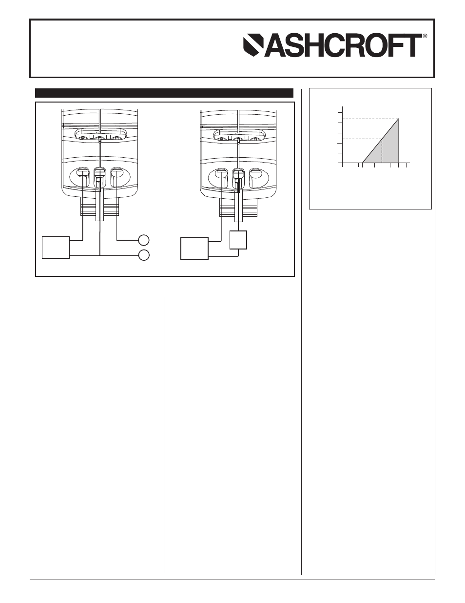
ELECTRICAL CONNECTIONS
Current Output
Voltage Output
Drawing #2
Vmin = 12V+ [.022A*(R L)]
*includes a 10% safety factor
RL = RS + RW
RL = Loop Resistance (ohms)
RS = Sense Resistance (ohms)
RW = Wire Resistance (ohms)
Load Limitations 4-20mA Output
0
10 12
20
30
36
40
1250
1091
1000
750
500
250
0
545
24
Drawing #3
Loop Resistance (
Ω
)
© 2011 Ashcroft Inc., 250 East Main Street, Stratford, CT 06614, USA • Tel: 203-378-8281, Fax: 203-385-0402 • email: [email protected], www.ashcroft.com. All specifications subject to change without
notice. All sales subject to standard terms and conditions of sale I&M011-10074 Rev A 5/11
ASHCROFT, INC.
250 EAST MAIN STREET, STRATFORD, CT 06614
TEL: 203-378-8281 • FAX: 203-378-0499
EMAIL: [email protected]
www.ashcroft.com
OPTION: SPOOLCAL™ (XPV)
The rotating process valve actuator in conjunction
with the SpoolCal™ actuator tool provides two
types of tests including Calibrate (CAL) and
Monitor (MON) through the appropriate Hi and Lo
Port of the SpoolCal actuator tool. In the (CAL)
mode the DXLdp is isolated from the process and
allows externally generated test pressure input for
calibration. In the (MON) mode the system pres-
sures can be monitored with an Ashcroft ATE
Calibrator or other handheld instrument without
physically unplugging the process tubes. In this
mode an on-line measurement can be captured. In
conjunction with the (XDL) option, a reference sig-
nal can also be captured without process interrup-
tion.
The (XPV) option supplies a SpoolCal™ actuator
tool and 7˝ of silicon tubing. The actuator tool
identifies the above positions and tests, including
high (HI) and low (LO) differential pressure reference.
From the (OFF) position the SpoolCal™ actuator
tool can be inserted and removed. The following
tests can be performed:
Calibration (CAL):
Both zero and Span adjustment pots are non-
interactive and accessible from the front of the unit.
Note: Due to the sensing technology used rarely
are actual zero and span adjustments needed.
Zero and span pots are available on the basic unit.
Requires XDL and XPV options.
• Insert SpoolCal™ actuator tool.
• A 90-degree clockwise rotation isolates the
DXLdp from the process.
• Apply zero pressure. This can be best produced
by shorting the HI and LO ports on the SpoolCal™
actuator tool using the silicon tubing supplied.
Verify or make zero adjustment.
• An external pressure generator can be used to
produce the required span pressure. Verify or
make span adjustment.
• Measure record signal via front access test jacks,
option (XDL).
Monitor (MON):
Provides on line or uninterrupted measurement
point capability when XPV option is again selected
in combination with the (XDL) option, including
the front access test jacks.
• Insert SpoolCal™ actuator tool
• A 90-degree counterclockwise rotation tee’s the
process to both the DXLdp sensor and out
through the SpoolCal™ actuator tool, to provide
external measurement or recording capabilities.
OPTION: 2:1 TURN DOWN (X21)
Provides optional in field scalability via internal
jumpers.
Example: Given a 1.0˝ DXLdp with 4-20mA output.
The unit can be adjusted to operate full scale at
0.5˝. In addition, the 4-20mA reference output
remains in calibration.
Steps (Following instructions on label):
1. Lay unit on right side. Remove reusable left side
label.
2. Pry off access door and discard.
3. Using needle nose pliers or twisters, move
jumper from top to bottom position.
4. Reattach label.
5. Reverse range label on face of unit.