General dimensions for model cxldp (in inches), I.d. tubing. (see figure 5) when, Zero and span potentiometers – Ashcroft CXLdp - Differential Pressure Transmitter User Manual
Page 2
MODEL CXLdp DIFFERENTIAL
PRESSURE TRANSDUCER
INSTALLATION & MAINTENANCE SHEET
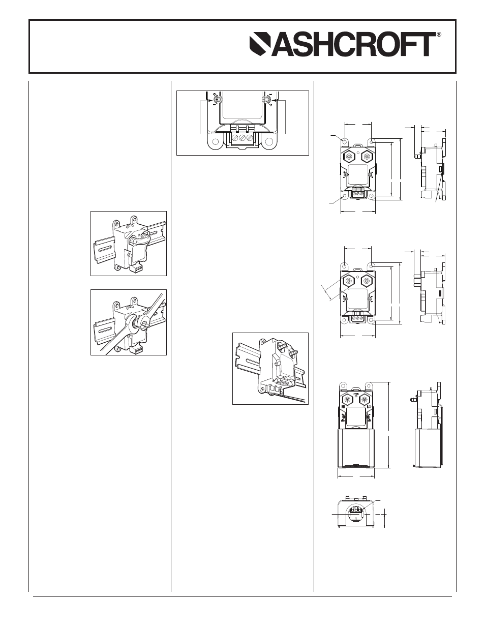
1.45
2.90
я .20
я .16
3.33
1.89
"B2" 1/4 BARB FITTINGS
1.32
.37
POWER
HI
LO
SPAN
ZERO
HOUSING TABS (2)
1.45
2.90
3.33
1.89
"01" 1/8 FEMALE NPT FITTINGS
1.32
.37
POWER
HI
LO
SPAN
ZERO
.56
MB2
1
⁄
4
˝ BARB FITTINGS
F01
1
⁄
8
NPT FEMALE FITTINGS
GENERAL DIMENSIONS FOR
MODEL CXLdp (in inches)
4.85
4.85
2.06
2.06
ASSEMBLED WITH 101A213-01 CONDUIT KIT
.78
.78
R
R .88
.88
ASSEMBLED WITH 101A213-01
CONDUIT KIT
4. Firmly reinstall the terminal block plug to its
mating connector.
Set Up:
Note: For best immunity from EMI the pressure
connection fittings on the CXLdp should not be
grounded.
The transmitters are calibrated at the factory in the
vertical position. Mounting in the horizontal posi-
tion can cause a zero shift of as much as ±1% F.S.
in ranges below 1 IW dp. Any minor zero offset can
be minimized using the zero adjust potentiometer
located on the front, left side of the instrument.
To find true zero differential pressure, pneumati-
cally connect the high and low pressure connec-
tions together using the tubing provided with the
transmitter. The
barbed connection
accept
1
⁄
4
˝ O.D.
1
⁄
8
˝
I.D. tubing.
(see Figure 5)
When
1
⁄
8
NPT fe-
male brass fittings
are used, do not
exceed 60 inch-
pound torque force
on female NPT fit-
ting.
When connecting to
the NPT fittings, do
not apply torque to
the CXLdp fitting.
Use a
9
⁄
16
˝ wrench to
hold the CXLdp.
(see Figure 6)
Zero potentiometer adjustment requires using a
3
⁄
32
˝
or 2.5 mm slotted or phillips screwdriver. The tub-
ing should remain in place until the transmitter is
to be connected to the BCS tubing system.
(see Figure 7)
Figure 5
Figure 6
Routine Maintenance:
The CXLdp is a very stable and reliable transmitter
incorporating a proven, micro-machined silicon ca-
pacitive sensor and a new, state-of-the-art applica-
tion specific integrated circuit (ASIC).
All calibration and temperature compensation func-
tions are done with a microprocessor and
digital routines.
To troubleshoot or verify performance, it is recom-
mended to pneumatically connect the pressure
ports to each other and establish a zero offset
reading in the as-installed position. Adjusting zero
will not affect span calibration.
Adjusting span should only be attempted when a
high accuracy pressure standard and high quality
electrical meter are able to be used.
DIN Rail Transmitter Removal:
In order to remove the transmitter when it is installed
on a DIN rail, it is necessary to first unplug the wiring
terminal block from the transmitter.
Insert a small slot-
ted screwdriver into
the black plastic
clip extending
slightly below the
transmitter case.
(see Figure 8)
Next, raise the
screwdriver handle
up thereby forcing
the spring clip down.
If questions or concerns need to be addressed, our
Low Pressure Product Manager or Engineering
Personnel can be contacted at (203) 378-8281 or
visit our website at www.ashcroft.com.
Figure 8
Figure 7
SPAN
ZERO
Zero adjust
potentiometer
Span adjust
potentiometer
Zero and Span Potentiometers
© 2011 Ashcroft Inc. 250 East Main Street 06614, Tel: 203-378-8281 • Fax: 203-378-0499, All specifications are subject to change without notice.
All sales subject to standard terms and conditions. www.ashcroft.com All rights reserved. I&M011-10130 Rev. A 10/12