K1, k2, k8 pressure transducer instruction sheet, K8 transducers – electrical connections, K1, k2 transducers – Ashcroft K8 - Industrial Pressure Transducer User Manual
Page 2: K8 transducers, Dimensions wiring diagrams for all transducers, Ratiometric (mv/v)
Special Wiring – See “X” Variation
On Unit Label
Variation
Wire Hookup
Red
=
+ Power
XTQ
Black
=
Common
White
=
Output
Red
=
+ Power
XTG
Black
=
Common
Green
=
Output
K8 Transducers – Electrical Connections
Hirschmann Type
PIN 1
= + Power
Red
PIN 2
= Common
Black
PIN 4
= Output
Green
Bendix 4-Pin, 6-Pin
Pin A
= + Power
Red
Pin B
= Output
Green
Pin D
= Common
White
Cable Type F2
Red
= + Power
White
= Common
N/A
Green
= Output
Cable Type C1
Red
= + Power
White
= Common
N/A
Green
= Output
Ratiometric (mV/V)
Cable Type F2
Red
= + Power
White
= – Power
Green
= + Output
Black
= – Output
4 Inch Leads
Red* = + Power
White
= – Power
Green = + Output
Blue
= – Output
*Orange = + Power, RoHS compliant
versions
Cable Type F2
Red
= + Power
White
= – Power
N/A
Green
= + Output
Black
= – Output
Cable Type C1
Red
= + Power
White
= – Power
N/A
Green
= + Output
Black
= – Output
Bendix 4-Pin
Pin A
= +Power
Red
Pin B
= +Output
Green
Pin C
= – Output
Black
Pin D
= – Power
White
Bendix 6-Pin
Pin A
= +Power
Red
Pin D
= – Power
White
Pin B
= +Output
Green
Pin C
= – Output
Black
Pin E
= Shunt Cal.
Pin F
= Shunt Cal.
Cable Type F2
Red
= + Power N/A
Black
= – Power
Cable Type C1
Red
= + Power N/A
Black
= – Power
Hirschmann Type
Pin-1
= + Power Red
Pin-2
= – Power Black
Bendix 4-Pin, 6-Pin
Pin A
= + Power Red
Pin B
= – Power Green
Current Output Units 4-20mA
Recalibration Instructions:
1. Apply 0% Full Scale Pressure.
2. Set the output using the Zero adjustment potentiometer.
3. Apply 100% Full Scale Pressure.
4. Set the output using the Span adjustment potentiometer.
5. Repeat steps 1 thru 4 as necessary.
3-Wire Voltage
4-20 mA
4-Wire Ratiometric (mV/V)
Ratiometric (mV/V)
Voltage Output Units 1-5, 1-6 Vdc
K2 Transducers – Electrical Connections
K1 Transducers – Electrical Connections
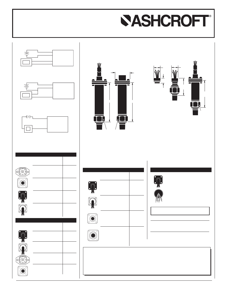
3.0
.625
HEX
6-PIN BENDIX
0.9 SQ.
-------------------
4-PIN BENDIX
0.8 SQ.
3.0
K1, K2 Transducers
0.5
0.34
0.5
1.1
2.1
.625
HEX
K8 Transducers
NOTE: All dimensions are decimal inches
Dimensions
Wiring Diagrams for All Transducers
K1, K2, K8
PRESSURE TRANSDUCER
INSTRUCTION SHEET
+
+
–
–
POWER
SUPPLY
(- Power)
(+ Power)
(- Output)
(+ Output)
METER
TRANSDUCER
RED
WHITE
GREEN
BLACK
+
+
–
–
POWER
SUPPLY
(Common)
(+ Power)
(+ Output)
METER
TRANSDUCER
+
+
–
POWER
SUPPLY
(+)
(–)
METER
TRANSDUCER
–
POWER
OUTPUT
MATING
CONNECTOR
CABLE CODING
CONNECTOR
TYPE
MATING
CONNECTOR
CABLE CODING
CONNECTOR
TYPE
MATING
CONNECTOR
CABLE CODING
CONNECTOR
TYPE
© 2012 Ashcroft Inc., 250 East Main Street, Stratford, CT 06614, USA. Tel: 203-378-8281 • Fax: 203-378-0499, All specifications are subject to change without notice.
All sales subject to standard terms and conditions. All rights reserved. www.ashcroft.com. I&M011-10063-1/01 (250-2924). Rev. A 7/12
(Blue, K8 only)