Nl;n – Ashcroft GC51 - Industrial Rangeable Pressure Transmitter User Manual
Page 2
Quick Start Function Summary Instructions
for ASHCROFT
®
GC51 Version 6.03
(See Complete I&M Manual for Further Detail)
C.
Re-scaling in “Arbitrary” units:
“Linear Display Mode”.
This function allows the user to establish a linear relation-
ship from the standard “psi” unit to any user defined unit.
Note:
See menu schematic at end, must be in “Linear
Display Mode” option within “Setting Mode”, this is
noted on the screen by
Use $ # keys to move between “Linear Display Mode”
and “Pressure Display Mode.”
© 2008 Ashcroft Inc., 250 East Main St., Stratford, CT 06614-5145, USA, Tel: 203-378-8281, Fax: 203-385-0499, www.ashcroft.com
All sales subject to standard terms and conditions of sale. 02/11 I&M011-10163_GC51_Rev. C_Ver. 6.03
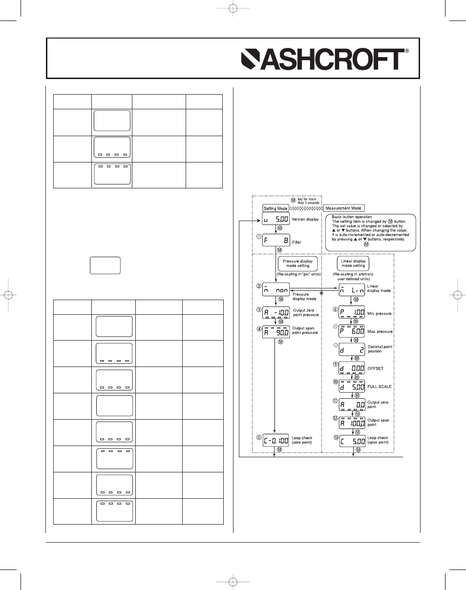
Note: Holding the
button for more than
3 seconds returns to display mode.
Complete Setting Mode Menu
n
L;n
d
0.00
d
5.00
d
2
p
60.0
a 100.0
a
0.0
p
10.0
-
Setting
LCD
Setting
Setting
Item
Display
Description
Range
Display
Selection of
non:pressure
mode
pressure display
display mode
mode : Lin
Lin:Linear display
mode
Minimum
Min. pressure
Pressure range
pressure
corresponding to
0 to 75% Span
OFFSET 9
: 10 (psi)
Maximum
Max. pressure
Pressure range
pressure
corresponding to
25 to 100% Span
FULL SCALE 10
: 60 (psi)
Decimal
Display after
0,1,2,3 digit
point
decimal point
position
Number of digits
: 2 (digit)
OFFSET
OFFSET
–1999 to 1999
corresponding to
min. pressure 6
: 0.00 (ton)
FULL
FULL SCALE
–1999 to 1999
SCALE
corresponding to
mAX. pressure 7
: 5.00 (ton)
Output
Analog output
Max. display
zero point
zero point (4mA)
span: –10
: 0.0 ( %Span)
to 110% Span
Output
Analog output
Max. display
span point
span point (20mA)
span: –10
: 100.0 (%Span)
to 110% Span
D.
Loop Check:
Use to send a 4-20mA signal meant to
simulate applied pressure, can be accessed either
through Pressure Display Mode or Linear Display Mode.
See “Complete Setting Mode Menu” at end. Loop Check
is noted on the screen with a prefix “
(
”. The display
is indicating in actual units and starts at the zero
(4mA) point.
If $ button continues to be pressed, the linear display
will auto-increment by linkage between the linear display
and the analog output. By continuing to press # button,
auto decrement will occur. Release the button at the
desired indication.
a
90.0
a
10.0
n
non
-
Note:
For setting of zero point and span point in the analog
output, input the percent value over the pressure range.
Setting
LCD
Setting
Setting
Item
Display
Description
Range
Display
Selection of
non:pressure
mode
pressure display
display mode
mode : non
Lin: linear
display mode
Output
Analog
Pressure
zero point
output zero point
range:–10
(4mA) : 10.0 (%Span) to 110% Span
.
Output
Analog
Pressure
span point
output span point
range:–10
(20mA) : 90.0 (%Span) to 110% Span
n
L;n
-
Notes shown below are from I&M manual.
Notes:
Actual values shown are based upon the examples
shown in the I&M Manual.
Changes made within the Setting Mode are saved
by returning to Measurement Mode before powering
the unit “off.”
Note:
Values shows are from example in I&M manual.
I&M011-10163-GC51 QS Rev. c:GC51–Quick Start
2/11/11 3:38 PM Page 2