Ashcroft A2X - Pressure Transmitter User Manual
Page 2
Power Supply
Power Supply Voltage
Output Signal
Min
Max
0-5Vdc
10V
30V
1-5Vdc
10V
30V
1-6Vdc
10V
30V
0-10V
14V
30V
4-20mA*
12V
30V**
* For transmitters with 4-20mA output
signal, the minimum voltage at the temi-
nals is 12Vdc. However, the minimum
supply voltage should be calculated
using the following graph and formula.
** For Intrinsically Safe Installations max,
supply voltage is 30Vdc. Refer to
Ashcroft drawing #825A022 for wiring
and installation requirements.
A2X EXPLOSION/FLAME PROOF
PRESSURE TRANSMITTER
INSTRUCTION SHEET
Mounting
The A2X transmitter requires no special
mounting hardware, and can be mounted
in any plane with negligible position error.
Although the unit can withstand normal
vibration without damage or significant
output effects, it is always good practice
to mount the transducer where there is
minimum vibration.
For units with NPT type pressure fittings
apply Teflon
®
tape or an equivalent
sealant to the threads before installing.
When tightening, apply a wrench to the
hex wrench flats located just above the
pressure fitting.
DO NOT tighten by using
a pipe wrench on the housing.
Noise
For minimum noise susceptibility, avoid
running the transducer’s leads in a con-
duit that contains high current AC power
cables. Where possible avoid running
the cable near inductive equipment.
Sintered Metal Filter
All units less than 500 psi include a small
metal sintered filter at the top of the unit.
This is necessary to equalize the internal
pressure with atmospheric pressure but
can be a point of moisture ingress.
Vmin = 12V+ (.022A x RL) (includes a 10% safety factor)
RL = RS + RW
RL = Loop Resistance (ohms)
RS = Sense Resistance (ohms)
RW = Wire Resistance (ohms)
10
1000
800
600
400
200
0
20
30
36
Operating
Region
30 Vdc max for
Intrinsically Safe
Installations
Loop Supply Voltage (Vdc)
Loop Supply Voltage vs. Loop Resistance
L
o
o
p
R
e
s
is
ta
n
c
e
(
O
h
m
s
)
+
+
–
POWER
SUPPLY
(+)
(–)
TRANSDUCER
–
V+
V–
PIN 1
PIN 2
4-20mA
METER
OR OTHER DEVICE
+
+
–
–
POWER
SUPPLY
METER
OR OTHER DEVICE
TRANSDUCER
(Common)
(+ Power)
(+ Output)
PIN 1
PIN 2
PIN 3
3-Wire Voltage
A2X Wiring Diagrams
A2X transducer has internal transient
protection: for safety, limit line-to-
ground voltage to 36 Vdc max.
© 2011 Ashcroft Inc. All rights reserved. 250 East Main Street, Stratford, CT 06614 USA Tel: 203-378-8281, Fax: 203-385-0402 www.ashcroft.com
All sales subject to standard terms and conditions of sale. I&M011-10167-A2X. Rev. 02/14
HAZARDOUS AREA CERTIFICATIONS
Explosion Proof* – cUL: Specify A2X
Class I, Div. 1 & 2, Groups A, B, C and D
Class II, Div. 1 & 2, Groups E, F and G
Flame Proof* – ATEX: Specify A2X
Compliance with standards
EN 60079-0: 2012
and
EN 60079-1: 2007
II 2 G
Ex d IIC T4 Gb
-40°C
≤ Tamb. ≤ 125°C
DEMKO 04 ATEX 0237942
Intrinsically Safe (applies to 4-20mA) FM/CSA:
Intrinsic Safety: Class I, II and III Div.1 and 2,
Groups A, B, C, D, F and G per
entity requirements see Ashcroft
drawing # 825A022
Non-Incendive: Class I, II and III Div.1 and 2,
Groups A, B, C, D, F and G, no
barriers needed
*
Model A2X enclosure is intended for
installation using metallic conduit and
requires installer to comply with appropri-
ate codes to complete proper installation
to meet the assigned hazardous area
designation.
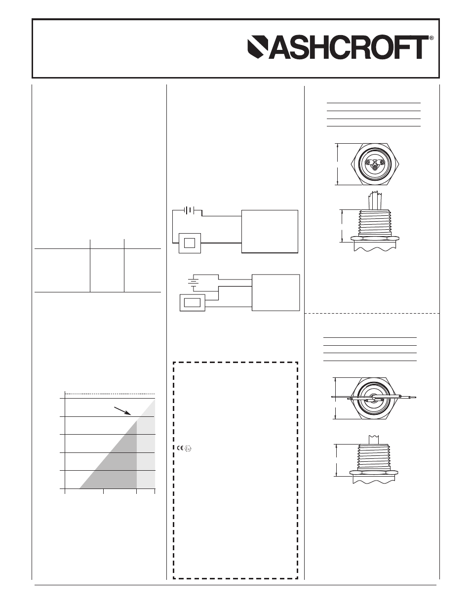
.830
FLYING LEADS
ELECTRICAL TERMINATION
CONDUIT - 1/2 NPT MALE
(C2), (C5)
E
1.062
Wire
Voltage
Current
Color
Output
Output
Red
(+) Power
(+) Power
White
(+) Output
None
Black
(-) Power
(-) Power
Wire
Voltage
Current
Color
Output
Output
Red
(+) Power
(+) Power
White
(+) Output
None
Black
(-) Power
(-) Power
.830
PIGTAIL
ELECTRICAL TERMINATION
CONDUIT - 1/2 NPT MALE
(C1), (P7)
E
1.062
SHIELDED CABLE (PIG TAIL)
ELECTRICAL TERMINATION
CONDUIT - 1/2NPT MALE
(C1), (C6), (C7), (P7)
*
Installation of conduit leads should be limit-
ed to 3m to maintain CE compliance