Installation instructions for ashcroft, Model 1134 differential pressure gauge/switch – Ashcroft 1134 - Differential Pressure Gauge User Manual
Page 2
SWITCH SETTING
Please follow these instructions when your differential pressure
instruments are supplied with switch.
Switch operation: Optional, reed switches are located adja-
cent to the pressure chamber and are activated by the magnet-
ic field of the sensor assembly.
Caution: Supply should not exceed switch rating. For higher
supply, use of relay circuit is recommended.
Switch adjustment: Switch adjustment screw is located on
plastic cover. Rotate the screw counter-clockwise to increase
the setpoint and clockwise to decrease the setpoint. One or
two trials may be necessary to attain the exact setpoint.
Above procedure to be followed by putting the instrument on
test bench or while in actual service.
Note: Instrument and switch has IP65 protection.
Installation Instructions for
ASHCROFT
®
Model 1134
Differential Pressure Gauge/Switch
© Ashcroft Inc., 250 East Main Street, Stratford, CT 06614-5145, USA, Tel: 203-378-8281, Fax: 203-385-0499, www.ashcroft.com
All sales subject to standard terms and conditions of sale. I&M008-10122-6/07 07/13
L or (+)
Load
N or (-)
1
3
2
E
L or (+)
N or (-)
N or (-)
Load for
Load for
Switch #1
3
2
E
1
Switch #2
B
R
E
1
3
2
SPST
Switch
3
1
E
R
B
2
B
Switch #1
Switch #2
Reed Switches and
DIN Plug Connection
View of socket for supply connections
Reed Switches and
DIN Plug Connection
View of socket for supply connections
SPST SWITCH (optional)
Specifications
Contact Rating
: 10 VA ac (rms) or dc (max)
Switching Current : 0.5 Amp ac (rms) or dc (max)
Switch Voltage
: 100 Vac (rms) or dc (max)
SPDT SWITCH (optional)
Specifications
Contact Rating
: 3 VA ac (rms) or dc (max)
Switching Current : 0.3 Amp ac (rms) or dc (max)
Switch Voltage
: 30 Vac (rms) or dc (max)
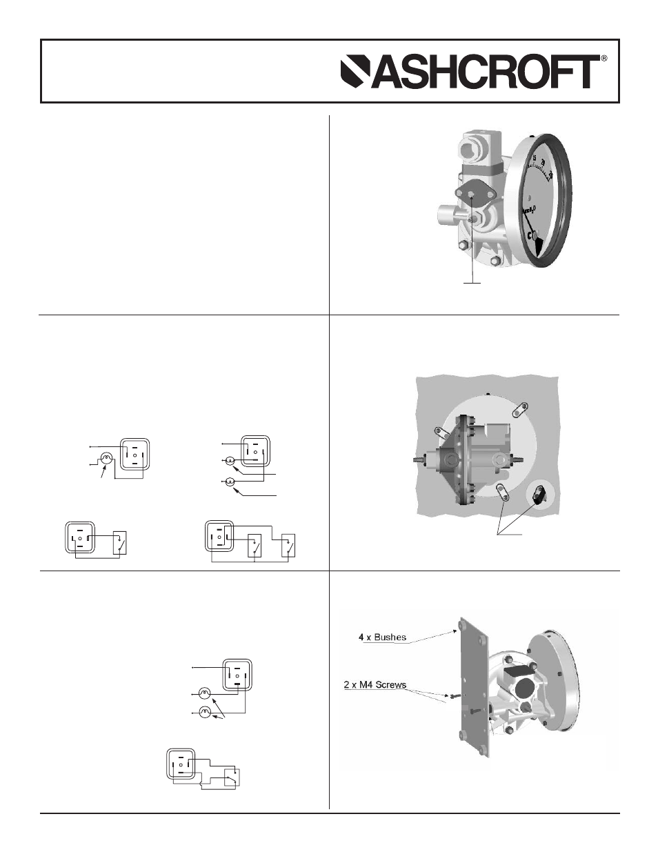
SURFACE MOUNTING (OPTIONAL)
Surface mounting plate and fasteners supplied with option.
Seal back ports with metal plugs supplied and clamp the
plate with two M4X10 screws on tapped holes of plugs.
FLUSH MOUNTING
Flush mounting kit contains three each of M3X4 and M3X20
screws with three flush mounting clamps.
One SPST switch
Two SPST switches
View of plug after removing the socket
Load
NC
NO
1
3
2
E
L or (+)
N or (-)
N or (-)
Y
R
3
1
2
E
B
SPDT
Switch
Reed Switches and
DIN Plug Connection
View of socket for supply connections
One SPDT switch
View of plug after removing the socket
View of plug after removing the socket
F
Panel cutout - 115 mm / 4.52˝
Flush mounting
clamp
R = Red; B = Black; Y = Yellow; L = Live or + Supply; N = Neutral or – Supply.
: 5 V
: 0.25 Amp AC (rms) or DC (max)
S
: 175 V AC (rms) or DC (max)
S
: 10 V
: 0.5 Amp AC (rms) or DC (max)
S
: 150 V AC (rms) or DC (max)
Model 1134 Flush Mounting Bracket
Model 1134 DGC Surface Mounting Option
SWITCH SETTING
View from high pressure side
Increased setpoint
counter clockwise
Decreased setpoint
clockwise