Installation instructions for ashcroft, Model 1132 differential pressure gauge/switch – Ashcroft 1132 - Differential Pressure Gauge User Manual
Page 2
Load
L
(+)
N
(-)
N
(-)
R
R
B
B
Switch #1 Switch #2
Load
L
(+)
N
(-)
R
B
Switch #1
6
6
5
5
4
4
3
3
2
2
1
1
6
6
5
5
4
4
3
3
2
2
1
1
L or (+)
L or (+)
Load
N or (-)
N or (-)
N or (-)
1
3
2
E
B
R
E
1
3
2
SPST
Switch
Load for
Load for
Switch #1
3
2
E
1
3
1
E
R
B
2
B
Switch #2
Switch #1
Switch #2
View of plug after removing the socket
View of plug after removing the socket
Installation Instructions for
ASHCROFT
®
Model 1132
Differential Pressure Gauge/Switch
© Ashcroft Inc., 250 East Main Street, Stratford, CT 06614-5145, USA, Tel: 203-378-8281, Fax: 203-385-0357, www.ashcroft.com
All sales subject to standard terms and conditions of sale. I&M008-10087-11/01 AMR 2C09/09
Load
NC
NO
1
3
2
E
N
(-)
L
(+)
N
(-)
L
o
a
d
L
o
a
d
N
C
N
O
B
R
Y
6
6
5
5
4
4
3
3
2
2
1
1
N
(-)
L
(+)
N
(-)
N
(-)
L
o
a
d
L
o
a
d
L
o
a
d
L
o
a
d
N
(-)
N
C
N
C
N
O
N
O
B
R
Y
Y
B
6
6
5
5
4
4
3
3
2
2
1
1
L or (+)
N or (-)
N or (-)
Y
R
3
1
2
E
B
SPDT
Switch
Switch #1
Switch #1 Switch #2
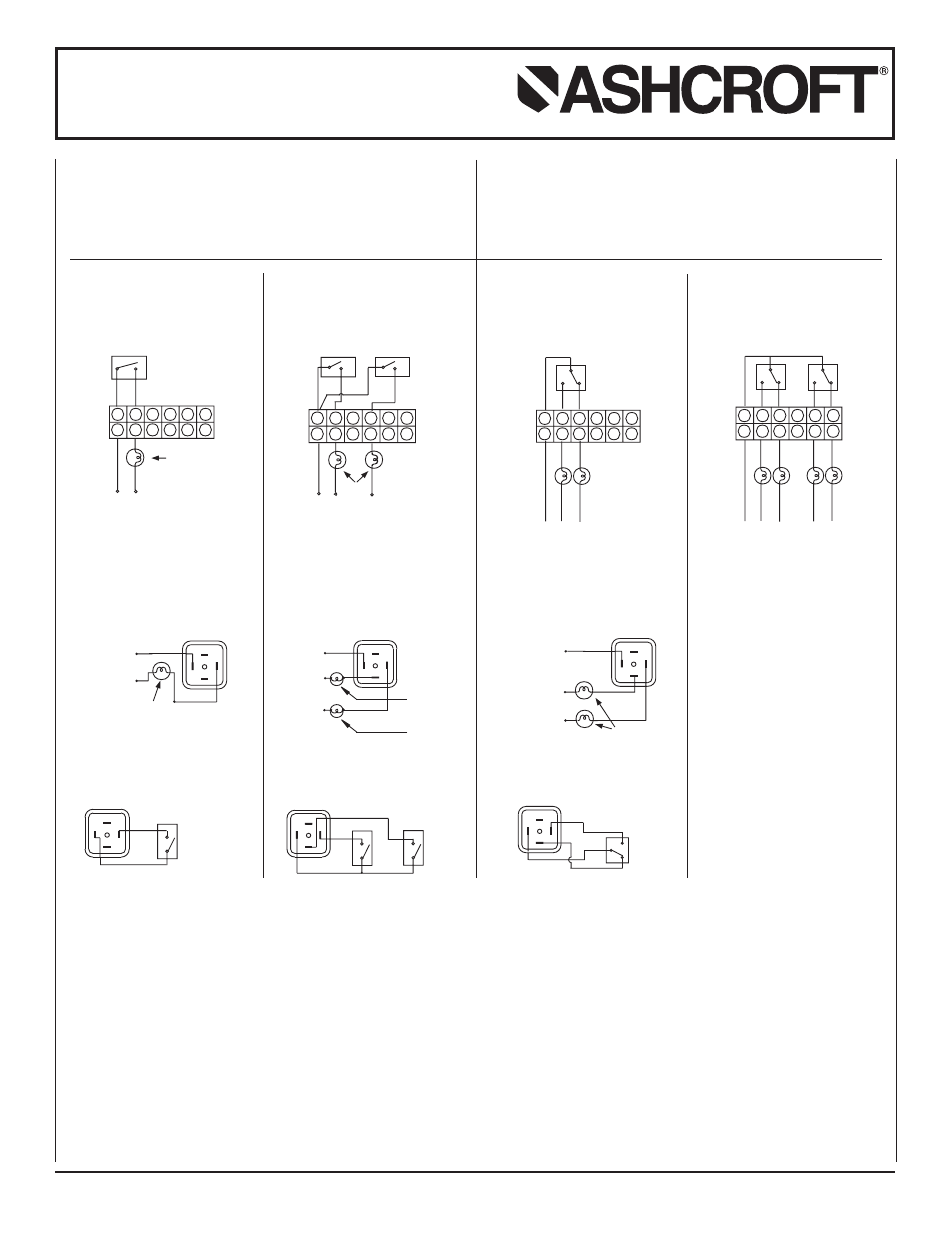
SPST SWITCH
Specifications
Contact Rating
: 10 VA ac (rms) or dc (max)
Switching Current : 0.5 Amp ac (rms) or dc (max)
Switch Voltage
: 100 Vac/Vdc (max)
SPDT SWITCH
Specifications
Contact Rating
: 3 VA ac (rms) or dc (max)
Switching Current : 0.3 Amp ac (rms) or dc (max)
Switch Voltage
: 30 Vac/Vdc (max)
ONE SPST SWITCH
Reed Switches and
Terminal Strip Connection
TWO SPST SWITCHES
Reed Switches and
Terminal Strip Connection
Reed Switches and
DIN Plug Connection
View of socket for supply connections
Reed Switches and
DIN Plug Connection
View of socket for supply connections
Reed Switches and
DIN Plug Connection
View of socket for supply connections
ONE SPDT SWITCH
Reed Switches and
Terminal Strip Connection
TWO SPDT SWITCHES
Reed Switches and
Terminal Strip Connection
View of plug after removing the socket
R = Red; B = Black; Y = Yellow; L = Live or + Supply; N = Neutral or – Supply.
*
Body to be suitably grounded while using gauge + switch and only switch.