Installation instructions for ashcroft – Ashcroft 1132 - Differential Pressure Gauge User Manual
Page 2
Load
L
(+)
N
(-)
N
(-)
R
R
B
B
Switch #1 Switch #2
Load
L
(+)
N
(-)
R
B
Switch #1
6
6
5
5
4
4
3
3
2
2
1
1
6
6
5
5
4
4
3
3
2
2
1
1
Installation Instructions for ASHCROFT
®
Explosion Proof Differential Pressure
Gauge/Switch, Variation XEK
Types 1130, 1131, 1132
© 2007 Ashcroft Inc., 250 East Main Street, Stratford, CT 06614-5145, USA, Tel: 203-378-8281, Fax: 203-385-0499, www.ashcroft.com
All sales subject to standard terms and conditions of sale. I&M008-10100-5/29 AMR 2C09/09
N
(-)
L
(+)
N
(-)
L
o
a
d
L
o
a
d
N
C
N
O
B
R
Y
6
6
5
5
4
4
3
3
2
2
1
1
N
(-)
L
(+)
N
(-)
N
(-)
L
o
a
d
L
o
a
d
L
o
a
d
L
o
a
d
N
(-)
N
C
N
C
N
O
N
O
B
R
Y
Y
B
6
6
5
5
4
4
3
3
2
2
1
1
Switch #1
Switch #1 Switch #2
SPST SWITCH
Specifications
Contact Rating
: 10 VA ac (rms) or dc (max)
Switching Current : 0.5 Amp ac (rms) or dc (max)
Switch Voltage
: 100 Vac/Vdc (max)
SPDT SWITCH
Specifications
Contact Rating
: 3 VA ac (rms) or dc (max)
Switching Current : 0.3 Amp ac (rms) or dc (max)
Switch Voltage
: 30 Vac/Vdc (max)
ONE SPST SWITCH
Reed Switches and
Terminal Strip Connection
TWO SPST SWITCHES
Reed Switches and
Terminal Strip Connection
ONE SPDT SWITCH
Reed Switches and
Terminal Strip Connection
TWO SPDT SWITCHES
Reed Switches and
Terminal Strip Connection
R = Red; B = Black; Y = Yellow; L = Live or + Supply; N = Neutral or – Supply.
*
Use ground screw to ground enclosure.
SWITCH SETTING
The switches are normally factory set to save time at customer
end. However, they are field adjustable.
CAUTION: Supply voltage should not exceed switch rating. For
higher voltages, the use of relay circuit is recommended.
SWITCH ADJUSTMENT
The following procedure can be done by putting the gauge on a
test bench or while in service.
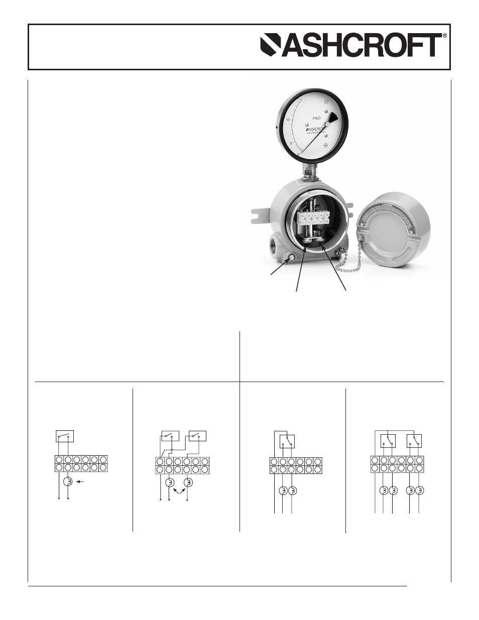
Unscrew the cover of the electrical enclosure. Knurled head set
screws are provided at bottom for setpoint adjustment .
Rotate the screw clockwise (right) to decrease the setpoint and
counter-clockwise (left) to increase the setpoint.
One or two trials may be necessary to attain the exact setpoint.
Switch #1
Set Screws
Ground Screw*
Switch #2
Set Screws