Aalborg DFM Digital User Manual
Page 32
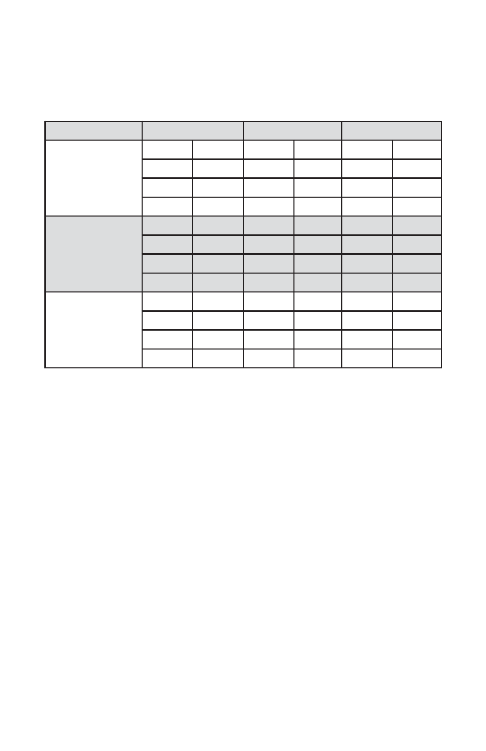
Analog output signals of 0-5 Vdc, (0-10 Vdc optional) or 4-20 mA are attained at
the appropriate pins of the 25-pin "D" connector (see Figure b-1) on the side of the
DFM transducer.
Table VI Analog Output Jumper Configuration
See APPENDIX IV for actual jumpers layout on the analog PCB.
6. MAINTENANCE
6.1 Introduction
It is important that the Mass Flow Meter is used with clean, filtered gases only.
Liquids may not be metered. Since the RTD sensor consists, in part, of a small
capillary stainless steel tube, it is prone to occlusion due to impediments or gas
crystallization. Other flow passages are also easily obstructed. Therefore, great
care must be exercised to avoid the introduction of any potential flow impediment.
To protect the instrument a 50 micron (DFM26/27) or 60 micron
(DFM 36/46/37/47) filter is built into the inlet of the flow transducer. The filter
screen and the flow paths may require occasional cleaning as described below.
There is no other recommended maintenance required. It is good practice, how-
ever, to keep the meter away from vibration, hot or corrosive environments and
excessive RF or magnetic interference. If periodic calibrations are required they
should be performed by qualified personnel and calibrating instruments, as
described in section 7. It is recommended that units are returned to Aalborg
7 for
repair service and calibration.
28
ANALOG SIGNAL
0-5 VDC
0-10 VDC
4-20 mA
Flow Rate Output
Jumper Header J2
J2.A
5-9
J2.A
5-9
J2.A
1-5
J2.B
2-6
J2.B
2-6
J2.B
2-6
J2.C
7-11
J2.C
7-11
J2.C
3-7
J2.D
8-12
J2.D
8-12
J2.D
4-8
Temperature Output
Jumper Header J3
J3.A
5-9
J3.A
5-9
J3.A
1-5
J3.B
2-6
J3.B
2-6
J3.B
2-6
J3.C
7-11
J3.C
7-11
J3.C
3-7
J3.D
8-12
J3.D
8-12
J3.D
4-8
Pressure Output
Jumper Header J4
J4.A
5-9
J4.A
5-9
J4.A
1-5
J4.B
2-6
J4.B
2-6
J4.B
2-6
J4.C
7-11
J4.C
7-11
J4.C
3-7
J4.D
8-12
J4.D
8-12
J4.D
4-8