Midco J121A-3 User Manual
Page 8
INITIATE (“POWER” LED is lit).
■
The RM7890 enters the INITIATE sequence when it is
powered. The INITIATE sequence lasts for ten seconds
unless the voltage or frequency tolerances are not met
(refer to Honeywell RM7890 literature for criteria). When
tolerances are met, the INITIATE sequence will restart. If
the condition is not corrected and the hold condition exists
for four minutes, the RM7890 will lock-out. causes for hold
conditions in the INITIATE sequence are in the Honeywell
RM7890 literature.
STANDBY (“POWER” LED is lit).
■
The RM7890 is idle in this state of sequencing. When the
burner switch, limits, operating limit controls, and all
microprocessor monitored circuits are in the correct state
for RM7890 to continue, sequencing will advance to
IGNITION TRIAL.
IGNITION TRIAL
1. PILOT FLAME ESTABLISHING PERIOD (PFEP)
A.
The pilot valve (“PILOT” LED will be lit) and spark
generator are energized.
B.
Flame must be proven by end of the 4 or 10-
second PFEP to allow the sequence to continue. If
flame is not proven by the end of PFEP, a safety
shutdown occurs.
2. MAIN FLAME ESTABLISHING
■
After the ignition trials, and with the presence of flame,
the main valve is energized. (“MAIN” LED will be lit.) If a
flame-out occurs, the RM7890 will lock-out or recycle within
.8 seconds. Refer to Honeywell literature for proper
configuration.
RUN
■
The RM7890 is now in RUN mode and will remain in run
mode until the controller input opens, indicating that the call
for heat has been satisfied or a limit has opened. Once this
occurs the RM7890 will sequence back to the STANDBY
mode.
Notes: 1.
During STANDBY
and during RM7890
sequencing the “POWER” LED will blink every
four seconds. This is normal.
2.
The “ALARM” LED will be lit in the event of
any flame failure.
3.
To maintain proper operation of this device it
MUST be electrically grounded. Refer to
Honeywell RM7890 literature for criteria.
XI SPECIAL EQUIPMENT (OEM VERSIONS)
Special equipment, either factory or field installed, can
cause variations in the procedures and descriptions given
in this manual. Generally, any burner ordered with special
factory installed equipment will be supplied with the
appropriate wiring diagram and related instruction manuals
from the special equipment manufacturer. Consult these
manual to identify any differences in construction,
operation, and testing. Field installed special equipment is
the responsibility of the installing contractor. For example,
when a high/low gas pressure switch is used, the high gas
pressure setting must be higher than the maximum
manifold pressure during initial start-up and the low
pressure setting must be set below the normal minimum
inlet pressure to prevent nuisance shutdowns during the
start-up procedure.
■
After the burner in started, the low pressure setting should
be raised until the burner shuts off. Reduce the setting and
set the low pressure switch to restart the burner. Reduce
the high pressure setting until the burner shuts off. Then
raise the setting slightly and reset the high pressure switch
to restart the burner. Do not make the adjustments too
close to trip points or nuisance shut downs may occur. Any
time the burner gas supply is shut off with the main manual
valve, the low pressure switch will require resetting.
■
IIf any doubt exists concerning burner operation when
special equipment is involved, contact the installing
contractor or MIDCO INTERNATIONAL INC. (front cover).
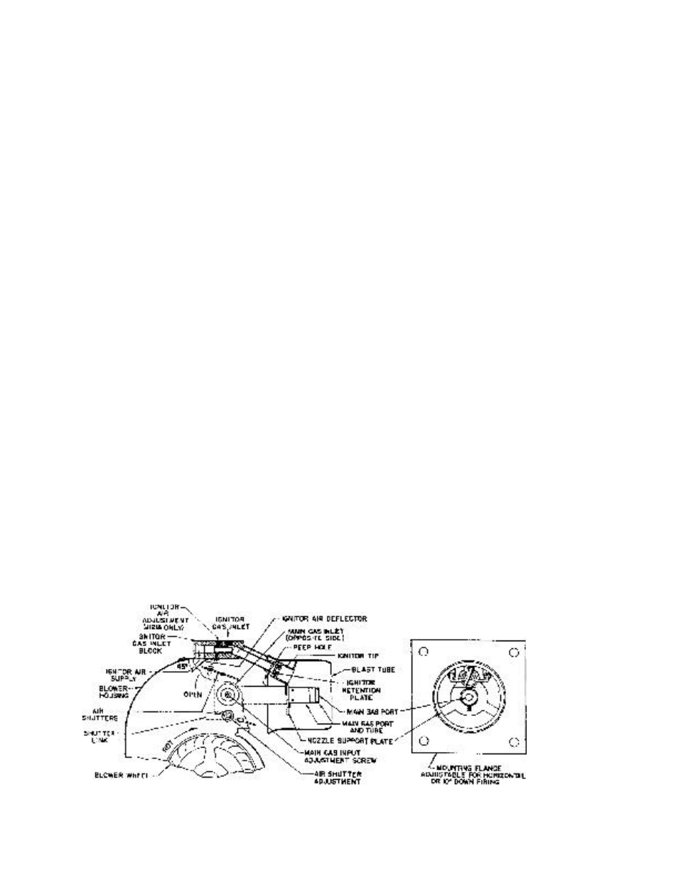
FIGURE 4
General Burner Head Assembly
-8-