Midco J121A-3 User Manual
Page 3
■
If the incinerator is designed only for No. 4 waste, the
level can be lowered to bring the flame to play directly on
the smaller loads characteristic of this type of operation.
The opening through which the burner fires should be of a
diameter only large enough to accommodate the Blast Tube
(4
1⁄4
" diameter x 3" minimum long.) Do not allow the Blast
Tube to protrude into the incineration chamber. If
necessary, build an extension outside of the incinerator wall
to increase wall depth.
■
To change the Mounting Flange to its alternate position,
horizontal or 10° down firing, remove the four (4) screws
that attach it to the burner, rotate the flange 180° and
reinstall the screws.
■
Before mounting the burner, check that the Blast Tube
and Blower Housing are clear of foreign material and that
the Main Gas Port and Nozzle Support is clean and
undamaged.
■
If the incinerator is located outdoors, the burner and all of
its components, except the Main Manual Shut-Off Valve,
must be protected from weather. The MIDCO Accessory
Weatherhood will provide such protection.
CAUTION: If the incinerator is of the down draft
design, make sure that a direct draft vent opening of
approximately 10 square inches has been put through
the top of the drop section(s) to provide for the venting
of any gas leakage. See Figure 1.
IV CHIMNEY, VENT CONNECTOR AND
DRAFT CONTROL
The size and type of material used for the vent connector
and chimney must conform to the recommendations of the
incinerator manufacturer, as well as local and national
codes. This is especially true where high flue gas
temperatures are encountered.
■
When natural draft is used and the chimney height is over
25 feet, a barometric damper of the same size as the vent
connector should be installed. If the chimney is high
enough to make it difficult for the barometric to maintain a
maximum incineration chamber over-fire draft, (0 to minus
0.5” W.C. for Model J81A-3, 0 to minus 1.0” W.C. for Model
J121A-3), a fixed damper should be installed in the vent
connector between the barometric and chimney to restrict
the chimney draft to a point within the controlling capacity
of the barometric. After final setting, the damper should be
permanently fastened into position per ANSI Z223.1-1992
"National Fuel Gas Code", or latest edition available from
American National Standards Institute to prevent
tampering.
V PIPING
The supply piping to the burner should branch off from the
main line as close to the source as possible (NATURAL
gas meter or PROPANE tank regulator). When branching
off from an existing gas line, do not tap off the bottom of a
horizontal section. Use new black pipe and malleable
fittings free from cutting and threading burrs or defects.
■
Use pipe joint compound resistant to liquid petroleum
gases when using either NATURAL or PROPANE gas.
Piping must comply with the local and national codes. If the
burner piping must be rearranged because of space
limitations, be sure to carry out the general configuration
shown in Figure 3.
■
A suitable Main Gas Pressure Regulator should be
installed as shown in Figures 1 or 3. Choose a regulator(s)
to adjust the available gas pressure to the pressure shown
in SPECIFICATIONS, page 2.
CAUTION: The regulated gas pressures must not
exceed 14:" W.C. or Main Automatic Gas Valve and
Ignitor Regulator will be damaged. If excessive gas
pressure is prevalent, the regulator must be a tight
shut-off type to prevent high pressures from
developing during stand-by. The regulator must have a
minimum flow regulating capacity for the ignitor gas
rate (see Table 4). It is strongly recommended that a
separate smaller regulator be used for ignitor gas,
connecting to the gas line ahead of the Main Gas
Pressure
Regulator
and
downstream
of
any
intermediate Regulator.
■
For full input, refer to SPECIFICATIONS, page 2, for
minimum gas pressure required. For reduced capacities,
refer to Firing Rate Curves, Table 2 or 3.
CAUTION: If gas supply pressure is below its
specified range during adjustment, an over-fire
condition could result when pressure returns to
normal, particularly if the regulator adjustment screw is
bottomed out. A LWAYS confirm that at least the
minimum rated pressure is being supplied during
regulator adjustments, and NEVER B O T TOM OUT
regulator screw.
■
When selecting the burner supply piping size per Table 1,
the permissible pressure drop must be based on the
pressure available at the inlet to the supply pipe branch line
when all other gas equipment fed by the same source
(NATURAL gas meter or PROPANE tank regulator) is firing
at full rate. Also take into account any other INCINOMITE
burners to be attached to the same branch line.
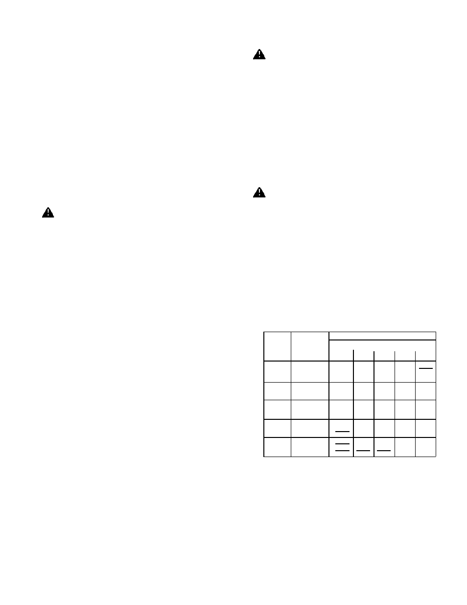
Capacities shown are for total pressure drop of 0.3"W.C. For
higher permissible pressure drops consult your fuel supplier.
Source: Gas Engineers Handbook-1974
Industrial Press Inc. NY, NY
TABLE 1
Schedule 40 Pipe Capacities in MBH
■
When pressure testing the supply piping, the burner
valve train must be protected. If the test pressure is 0.5
PSIG or less, closing the Main Manual Shut-Off Valve will
suffice.
NPT
PIPE
SIZE
3⁄4"
1"
1-1⁄4"
1-1⁄2"
2
TYPE
OF GAS
NATURAL
PROPANE
NATURAL
PROPANE
NATURAL
PROPANE
NATURAL
PROPANE
NATURAL
PROPANE
10
275
450
520
820
1050
1200
1200
20
200
300
350
550
730
1150
1100
1200
1200
40
130
200
245
385
500
790
760
1200
1200
60
100
165
195
300
400
630
610
960
1150
1200
100
125
150
235
300
480
460
725
870
1200
APPROXIMATE CAPACITY-MBH
LENGTH OF PIPE/FEET
-3-