Vii main gas spud, Viii initial start up/adjustment – Midco RE32 User Manual
Page 5
VII MAIN GAS SPUD
Standard burners are approved for use with NATURAL or
PROPANE gas and should be used only with the gas specified
on the rating plate.
■
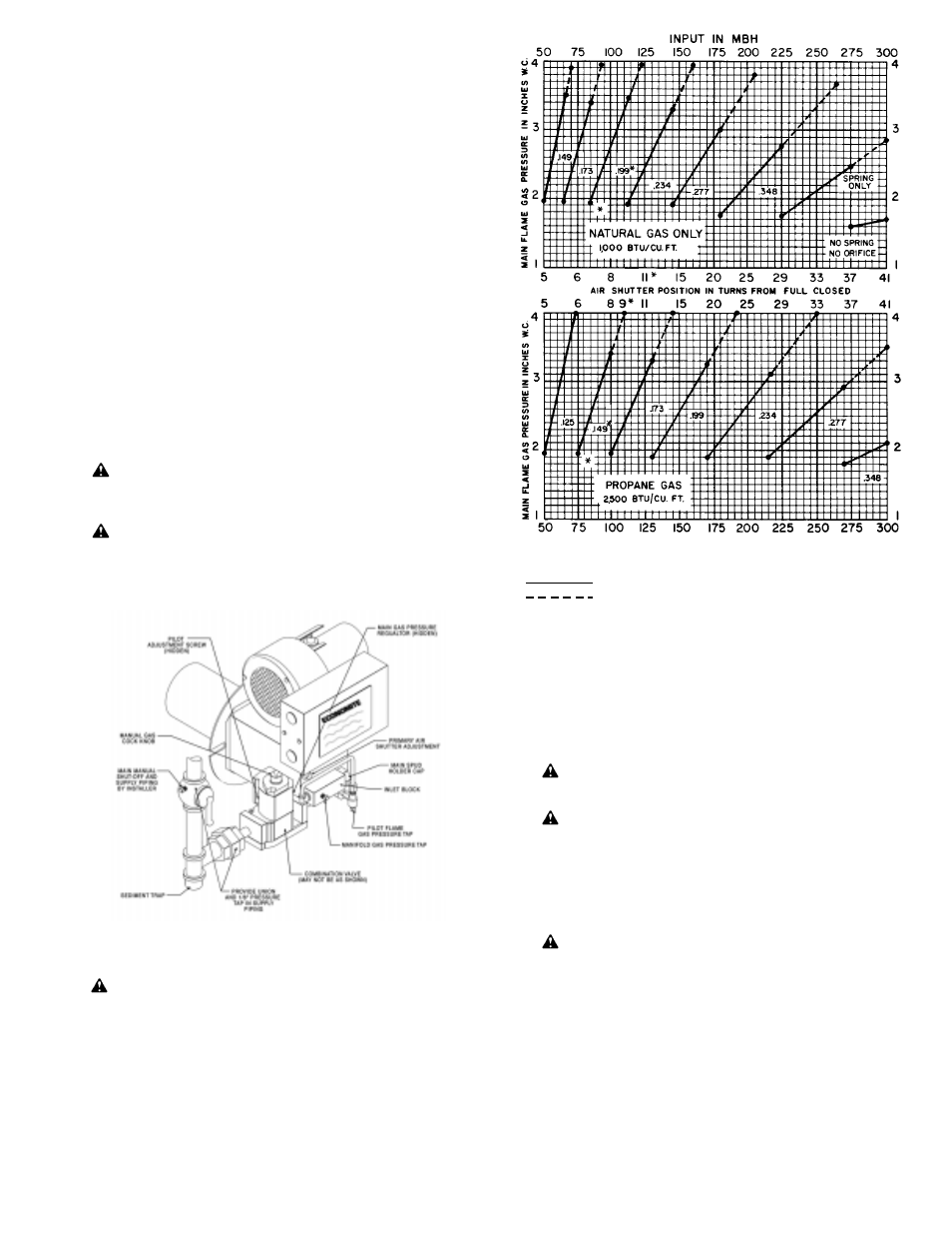
As shipped, the installed NATURAL gas spud has a #8
(.199) drill orifice size (PROPANE a #25 [.149]), for an input
capacity range of approximately 85 to 125 MBH (PROPANE 75
to 110 MBH). The combination valve main gas pressure
regulator is set to provide 2.0" W.C. manifold gas pressure for a
minimum spud input and the blower air shutter is set for
maximum spud input, 11 turns from full closed (PROPANE 9
turns), to provide a lean gas/air mixture for initial start up.
■
If a standard NATURAL gas Model RE32 is to be used with
PROPANE gas, a conversion kit which contains a .025 Pilot
Spud, a 1/8" main spud and a PROPANE label is available.
Change the pilot spud, affix the PROPANE label over the NAT
designation on the rating plate and install the appropriate size
main spud as detailed below.
■
If the required firing rate does not fall within the range of the
installed spud, or if converting to PROPANE gas, select the
correct capacity range from Table 3 and, if so indicated, the
spud with the correct orifice size (stamped with inch diameter)
from the spare spud bag. If the required firing rate is at the
minimum of capacity range, select the next lower range.
■
Remove the installed spud and spring assembly, select new
spud and assemble to spring, install assembly (spud first),
spring only or neither, as shown for the capacity range
selected per Table 3.
WARNING: Reposition the primary air shutter for the
maximum firing rate of the selected capacity range. Do not
change the combination valve main gas pressure regulator
setting at this time.
CAUTION: The approximate air and gas settings
described above are for initial start up only. Final settings
must be made in accordance with Section VIII.
Instructions for adjustment of the manifold gas pressure
are detailed in Section XI.
FIGURE 7 Piping Connections
VIII INITIAL START UP/ADJUSTMENT
WARNING: Ignition is automatic. Make spark
observations into combustion chamber only with Main
Manual Shut-Off Valve closed. Confirm that gas utilization
equipment does not contain any accumulated gases.
Purge as described in Step 3 below.
NOTE: Standard burners are shipped with the combination
valve pilot adjustment set to provide a permissible pilot flame
gas pressure when the gas pressure at the inlet to the
combination valve is within 4.0" - 6.0" W.C. NATURAL and
PROPANE. If the inlet gas pressure is not suitable, refer to
TROUBLE CHART, Section II.C.
*Spud orifice size and approximate shutter and manifold
gas pressure settings; as shipped.
Orifice range with 4.0" W.C. inlet pressure
Orifice range with 5.0" W.C. inlet pressure
Data shown is approximate and based on "0" overfire
pressure at sea level.
TABLE 3: Spud Capacity and Preliminary Gas
and Air Settings
1. Check the burner piping and valves for gas leaks by
applying a weak liquid soap solution to unions and joints
with the gas supply on. Leakage will be indicated by the
appearance of soap bubbles. Locate and correct all gas
leaks before proceeding.
WARNING: DO NOT USE OPEN FLAME.
2.
Purging the air from the gas line at this point will
expedite the first start as described below.
CAUTION: Purge outside the building. Do not
purge into the gas utilization equipment.
3.
To purge the gas utilization equipment and chimney of any
accumulated gases, turn Manual Gas Cock Knob on the
Combination Valve to OFF, turn burner power ON and set
the operating control to ON or thermostat to call for heat.
Let the
blower run long enough to accomplish four air
changes but not less than five minutes.
4.
CAUTION: Make sure that the capacity range of
the installed spud, and the preliminary gas pressure is
suitable for the input rating of the gas utilization
equipment. See Section VII and Table 3.
5.
Reset the Electronic Control by setting the operating
control to OFF or the thermostat below room
temperature for at least 60 seconds. See Section XII.
6.
Turn Manual Gas Cock Knob on Combination Valve to ON.
7.
Turn operating control to ON or set thermostat above room
temperature. A few seconds after the motor reaches
operating speed the pilot should light, followed by the main
flame. If the burner fails to light within 90 seconds, the
Electronic Control will shut off the pilot and main valves
and will lock out. To reset the Electronic Control for
restart, de-energize the control by setting the operating
-5-