Part 1 installation, Specifications, Iii combustion chamber – Midco RE32 User Manual
Page 2: I ventilation, Ii preparation of the gas utilization equipment
around door frames, to prevent leakage into or out of the
combustion chamber.
■
The access or firing door should open easily to relieve
pressure. If positive latches exist, they should be modified to
permit easy opening; a spring loaded door holder is
recommended.
■
On all boilers, make certain the pressure relief safety valve is
in good operating condition.
III COMBUSTION CHAMBER
A combustion chamber liner is normally required to protect
non-heat transfer surfaces and to provide a radiant bed for
rapid heat transfer to the primary surfaces of the heat
exchanger. In most cases an existing oil burner combustion
chamber liner can be used, if in good condition.
■
In the case of wet base boilers, where the entire combustion
chamber is comprised of heat exchange surfaces and no
combustion chamber liner was provided for oil firing, a liner is
usually not required for the ECONOMITE. However, a liner or
target wall may be necessary if the combustion chamber is
unusually short, in order to avoid excess flame contact on the
heat exchanger walls or flueways.
■
If a built up combustion liner is required, use 2300oF
minimum insulating material.
■
The opening in the combustion chamber must fit the burner
tube. If an existing chamber with an oversized opening is to be
used, fill the remaining space around the tube with refractory
material and seal air tight.
NOTE: In no case should the burner tube be allowed to extend
into the chamber proper; it must be set flush to 1/4" short of the
inside surface, because high combustion chamber
temperatures will cause premature pilot deterioration.
■
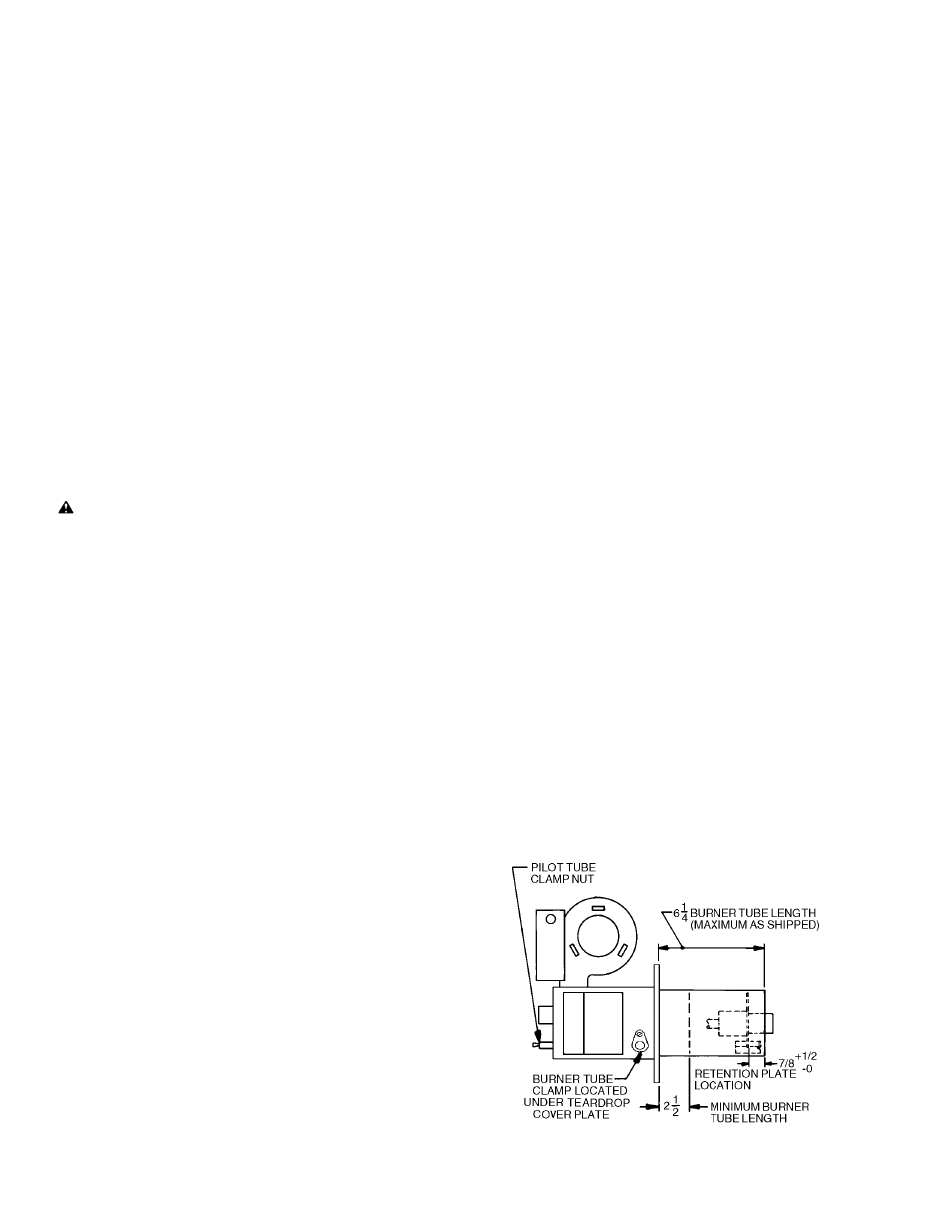
Burners are shipped with the burner tube at its fully extended
length of 6
1/4
inches. To reduce the tube length, complete the
following steps (see Figure 1):
1.
Uncover the Burner Tube Clamp access port located on the
lower right side of the burner box (under motor),
adjacent to the mounting flange.
2.
Turn the exposed screw counter-clockwise to loosen
the Burner Tube Clamp.
3.
Turn the Pilot Tube Clamp Nut (see Figure 1)
counterclockwise, to loosen the Pilot Tube.
4.
Push Burner Tube in to desired length and tighten
Burner Tube Clamp and recover access port.
5.
Locate the retention plate at least 7/8 inch but not more
than 1
3/8
inch from the end of the burner tube and tighten
the Pilot Tube Clamp Nut.
6.
Cut the Pilot Tube to the appropriate length and
reattach tube fitting using compression sleeve supplied in
spud-bag.
FIGURE 1
Burner Tube Adjustment
-2-
SPECIFICATIONS
NATURAL or PROPANE Gas
AIR DELIVERY
(Approx. Air Delivery at Zero Draft)
.....62SCFM*
MAXIMUM FIRING RATE**................................300MBH***
MINIMUM FIRING RATE**...................................50MBH***
TUBE DIAMETER................................................4 inches
TUBE LENGTH......................................2
1/2
- 6
1/4
inches
MINIMUM COMBUSTION CHAMBER SIZE
300 MBH...................................7" W x 11" L or 10" dia.
50 MBH.....................................6" W x 10" L or 9" dia.
GAS PRESSURE REQUIRED
NATURAL..........................................4.0" to 14.0"W.C.
PROPANE.........................................4.0" to 14.0"W.C.
STANDARD VOLTAGE..........120 Volts.............60 Cycle
PILOT SAFETY.........................Electronic, 100% shut-off
MAIN AUTOMATIC VALVE...........4 Function Redundant
*SCFM = Standard Cubic Feet/Minute
**All Ratings Based on 1000 BTU/Cu. Ft. NATURAL, 2500
BTU/Cu. Ft. PROPANE at Sea Level Derate burner for
altitudes over 2,000 feet by 4% for each 1,000 feet above
sea level
***1 MBH = 1,000 BTU/Hr.
One gallon fuel oil = 140,000 BTU/Hr.
PART 1
INSTALLATION
CAUTION: The ECONOMITE RE32 is not intended for
outdoor installation and must be protected from excessive
moisture. Provide adequate clearance for service and
proper operation.
I VENTILATION
If the former automatic oil burner gave trouble-free operation, it
is probable that the gas utilization equipment area has sufficient
infiltration of air for combustion and dilution of flue gas.
Nevertheless, the area must be checked:
■
Open basement or utility areas of normal construction,
without storm windows or tight doors, will generally allow
sufficient air infiltration. However, if the gas utilization
equipment is located in a tight or separate room, ventilation to
an open area as described above will be required. Install two
permanently open grilles, each sized on the basis of one
square inch free area per 1,000 BTU (but not less than 100
square inches) of the total input ratings of all gas utilization
equipment in the combined space. One grille should be located
within 12 inches of the ceiling, the other within 12 inches of the
floor.
■
If the gas utilization equipment is located in an area of
unusually tight construction, or if an exhaust fan, kitchen
ventilation system, clothes dryer and/or fireplace is installed in
the building, provision must be made for an outside air supply
near the gas utilization equipment area. Install permanently
open grilles sized at not less than one square inch free area per
4,000 BTU of burner input. When ventilating through horizontal
ducts, grilles should be sized at not less than one square inch
free area per 2,000 BTU of burner input. In any case, the
minimum dimension of rectangular air ducts shall not be less
than 3 inches.
■
In Canada, for detailed ventilation requirements, refer to
standard CAN/CGA 1-B149.1 or .2 and/or local codes.
II PREPARATION OF THE GAS
UTILIZATION EQUIPMENT
■
Clean the gas utilization equipment heat exchanger interior,
combustion chamber and flue connections. Remove all
adhering tars, scale, dirt and soot. Inspect equipment for actual
leaks and/or potential leaks.
■
Cement all joints, including those in the equipment base and