Part 1 installation – Midco Economite RE4400B / RE4400BA User Manual
Page 8
____________________________________________
Burners are approved for use with NATURAL gas or PROPANE gas and should be used only
with the gas specified on the rating plate.
The gas input should be set at the heating rate determined by the building heat loss and/or
heating plant survey, but not exceeding the rated maximum input of the gas utilization
equipment or Economite burner.
____________________________________________
WARNING: Ignition is automatic. Make spark observations into combustion
chamber only with Main and Pilot Manual Shut-Off Valves closed. Confirm that gas
utilization equipment does not contain any accumulated gases. Purge as described in
step 3 below.
CAUTION: Cover plates, guards, and enclosures must be maintained in place at
all times except during maintenance and service.
1.
Check the burner piping and valves for gas leaks by applying a weak liquid soap
solution to unions and joints with the gas supply on. Leakage will be indicated by the
appearance of soap bubbles. Locate and correct all gas leaks before proceeding.
WARNING: DO NOT USE OPEN FLAME.
2.
Purging the air from the gas supply line at this step will expedite first light-off.
IMPORTANT: Purge outside the building. Do not purge into the gas utilization
equipment.
3.
To purge the gas utilization equipment and chimney of any accumulated gases, turn
main Manual Gas Cock OFF, close Pilot Manual Shut-Off Valve, turn burner power on,
and set operating control to ON or thermostat to call for heat. Let the blower run long
enough to accomplish four combustion chamber volume air changes, but not less than
five minutes.
CAUTION:Make sure that the capacity range of the burner, manifold pressure,
and the combustion air shutter setting are suitable for capacity rating of the gas
utilization equipment. Refer to Section VIII and Table 3.
4.
RESET the Ignition Control Module by setting the operating control to OFF or the
thermostat below room temperature for at least 30 seconds. See Section XII.
5.
Confirm that Main and Pilot Manual Shut-Off Valves are open. Turn main Manual Gas
Cock ON.
8
Part 1
Installation
Continued
Part 1 Installation
VII
Main Gas
Input Selection
VIII
Initial Start-
up /Adjustment
VI
Piping
Continued
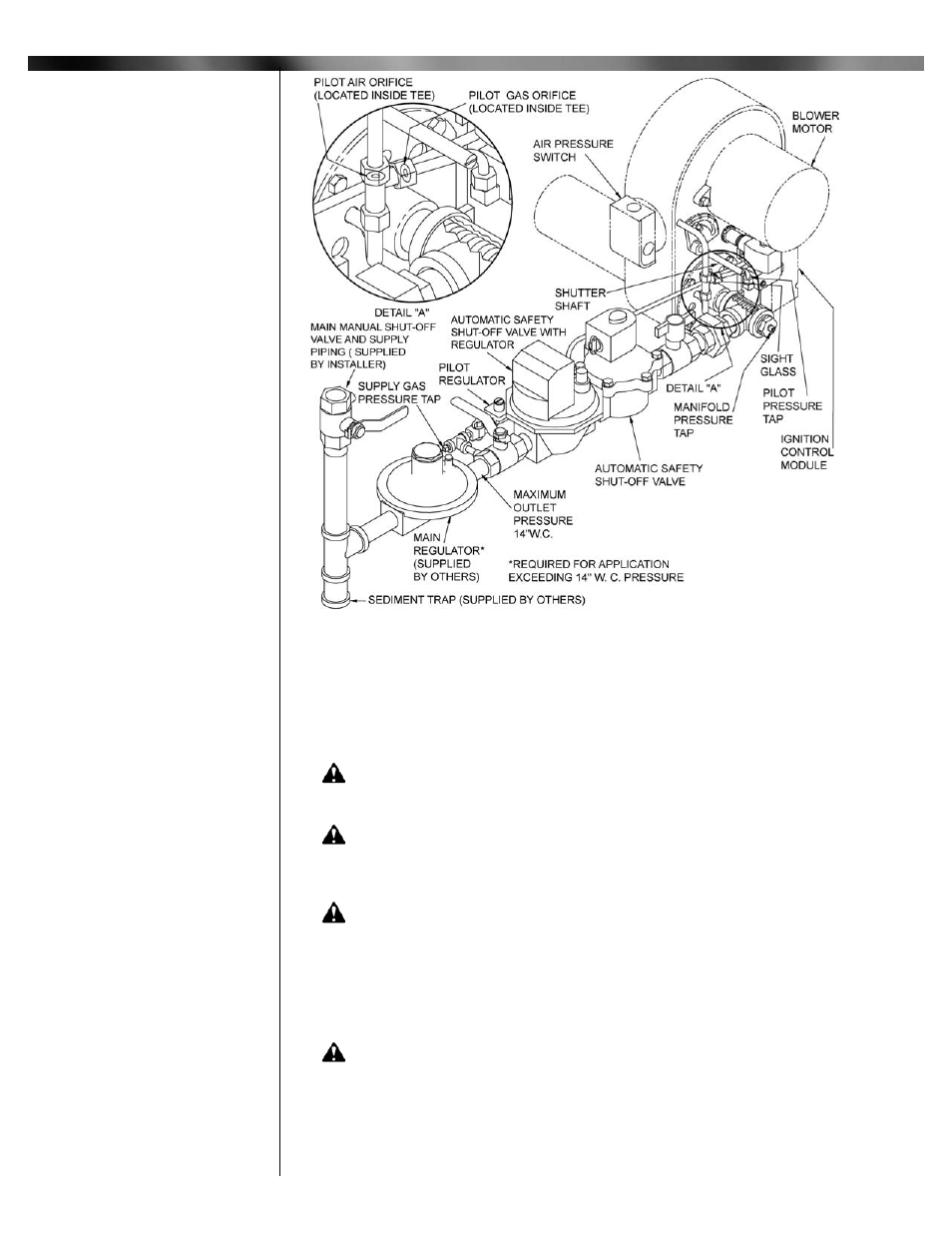
RE4850BA UL, Valve Train
Assembly 24VAC
Figure 5: Piping Diagram (Continued)