Part 2 service – Midco Economite RE4400B / RE4400BA User Manual
Page 13
Part 2 Service
A. No voltage: Interlock circuit OK.
B. Voltage present: check that the switch is wired properly or check switch
operation. Replace if switch tests bad.
____________________________________________
Should replacement or service be required, valve manufacturer's instructions must be
followed as outlined in their information sheet.
Outlet pressure settings must be checked while the gas is flowing.
To adjust outlet pressure, remove the seal cap for access to the adjusting screw. Turning the
screw clockwise will increase outlet pressure, counter clockwise will decrease outlet pressure.
____________________________________________
Prepurge S8670J
When power is applied to L1 and L2 through a safety and operating control, the combustion
air blower starts, once the air proving switch closes and proves blower operation, energizes
the S8670J, and initiates a 30 second delay to allow system prepurge. After a 30 second
prepurge, the 15 second trial for pilot ignition sequence begins.
Trial for Pilot Ignition
On a “call for heat” and after 30 second prepurge, the module energizes the spark source and
the pilot valve relay simultaneously. The pilot valve opens, allowing gas to flow to the pilot
burner during the 15 second ignition trial time. The spark lights the pilot flame when pilot gas
is present. A flame rectification circuit confirms the presence of the pilot flame, shuts off the
spark source, and energizes the main valve relay.
Main Burner Operation
When the main valve opens, gas flows to the main burner where it is lit by the pilot flame.
There is a 2 second flame stabilization period as the main valve opens. The system is now in
the run mode with the presence of the pilot flame continuously monitored by the flame
rectification circuit. If the pilot flame goes out, or pilot flame signal drops below 1.1micro
amps, the control senses loss of pilot flame and shuts off both the pilot valve relay and the
main valve relay.
The control has two LEDs; one for flame sensing and one for system status:
. Flame LED (Yellow)
. Indicates flame presence and strength.
. Status LED (Green)
. Indicates system operation status and error conditions.
FAILED TRIAL FOR PILOT IGNITION S8670J
If pilot flame is not lit and sensed before the end of the15 second trial for ignition time, the
control shuts off the pilot valve (100% shutoff) and goes to lockout. Or if proof of flame is lost
during burner run cycle the system will retry once, if pilot flame is not proven within the 15
second trial for ignition time, the control shuts off the pilot valve relay and lockout. The control
remains in lockout until power is cycled by the system thermostat or removing and restoring
system power.
For operation characteristics, maintenance, service procedures, and LED codes refer to
manufacturer’s literature provided.
WARNING: Explosion hazard. Do not use any electronic device if it gets wet.
It can malfunction and cause serious injury or death. Replace any device that has
been wet.
____________________________________________
XI
Valve Train
XII
Sequence of
Operation
S8670J Ignition
Control Module
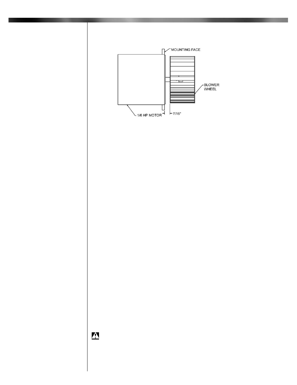
Figure 6: Motor / Blower Assembly
Part 2
Service Continued
13
X
Motor Blower
Interlock
Continued