Switch a, Table 3-5. switch a – MagTek HALF CARD PORT User Manual
Page 31
Section 3. Commands, Formats, Timing
23
Switch A
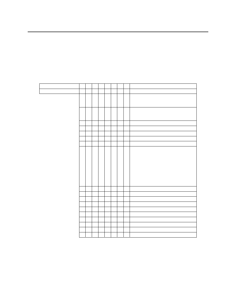
Switch A, Table 3-5, is primarily used to define the communication settings. The default for
Switch A is:
11100010
9600, no parity, 8 bits, send ID at power on, transmit SS & ES
Table 3-5. Switch A
Command position 1
2
3
4
5
6
7
8
Byte Position
7 6 5
4
3
2
1
0
Description
0
0
0
Baud rate 2400 (This setting may
draw too much power from the host
so it should be avoided if possible.)
0
0
1
Baud rate 4800 (This setting may
draw too much power from the host
so it should be avoided if possible.)
0
1
0
Baud
rate
9600
0
1
1
Baud
rate
14400
1
0
0
Baud
rate
19200
1
0
1
Baud
rate
38400
1
1
0
Baud
rate
57600
1
1
1
Baud rate 115200 (If the device is
put into this setting, it will no longer
be able to receive commands
unless the characters sent to the
device are spaced apart such that
there is at least 100µs of idle time
between each character. For this
reason, this setting should be
avoided if possible.)
0
0
No
parity
0
1
Even
parity
1
0
Odd
parity
1
1
Mark (Parity = 1 all the time)
0
7
bits
data
length
1
8
bits
data
length
0
Send ID at power on: No
1
Send ID at power on: Yes
0 Transmit
SS
and
ES:
No
1 Transmit
SS
and
ES:
Yes