A.O. Smith BFM 80 User Manual
Page 18
18
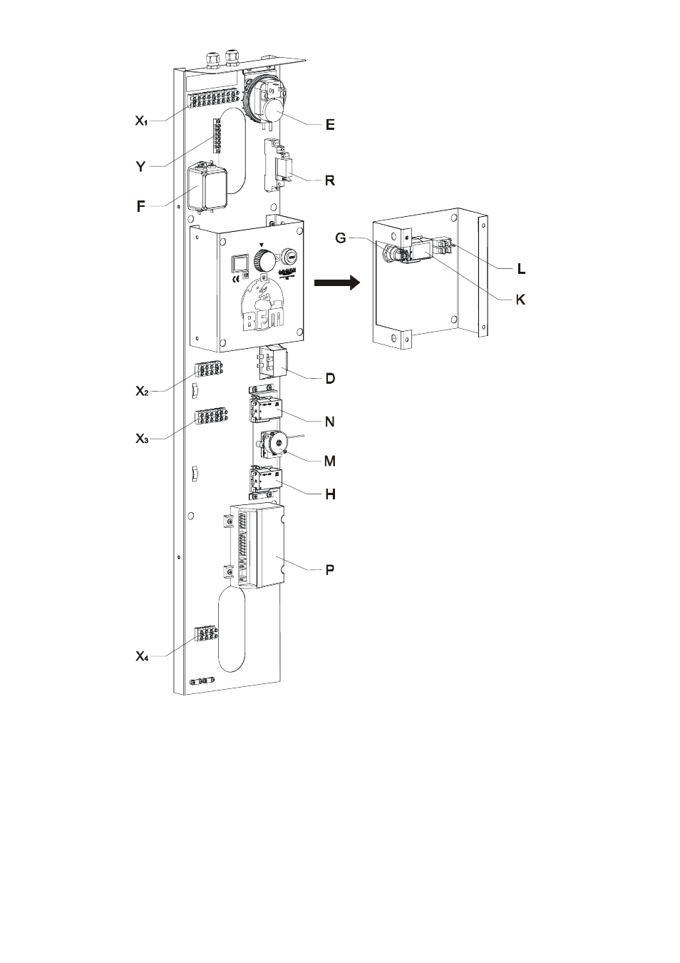
Figure 13 - Connection diagram control-column.
D) Transformer 230
E) Air proving switch
F)
EMC single phase filter
G) RESET knob
H) Thermostat frost
K) Thermostat regulation
L)
Switch ON/OFF
M) Thermostat overheat
N) Thermostat high limit
P) Automatic burner controller
R) Relay
X)
Plastic connector strip
Y)
Earth terminal block
IM D -0 06 3
See also other documents in the category A.O. Smith Water boiler:
- ACGSS02407 (4 pages)
- 401 (48 pages)
- 6-119 (28 pages)
- 1850 (36 pages)
- ADMP - 60 (6 pages)
- 750 (24 pages)
- 505 (2 pages)
- BTX-100 (2 pages)
- GW/GWO-2500 (4 pages)
- NW 37-670 (12 pages)
- BTP(V)-740A (6 pages)
- Genesis GB-1500 (2 pages)
- VWT-1000 (4 pages)
- AOSTT35300 (4 pages)
- 1300 (12 pages)
- BTP-199 (4 pages)
- ADM - 135 (74 pages)
- 1000 (80 pages)
- BTH-500A (8 pages)
- BTH 400A (36 pages)
- BTH 300A (36 pages)
- DB-720 thru 1810 (4 pages)
- BTP-378A (2 pages)
- BTI 120 (32 pages)
- AOSRG45300 (2 pages)
- AOSRG46600 (2 pages)
- VB/VW- 750 (52 pages)
- 300A (40 pages)
- 185363-001 (32 pages)
- AOSRE50400 (2 pages)
- TC-099 (74 pages)
- 25 litres (11 pages)
- ATI-705N (2 pages)
- XGV-50 200/201 (2 pages)
- 12 50GPC T 100 (56 pages)
- GB/GW-200 (10 pages)
- GWT-2500 (4 pages)
- VB 750 (8 pages)
- BTH 400 (1 page)
- 000 (4 pages)
- LB/LW: 500 (12 pages)
- VW-500 through VW-1000 (4 pages)
- BT-100 (2 pages)
- BTI-80 (2 pages)
- Voltex Hybrid Electric PHPT-80 (20 pages)